A kind of ff oil tank production process

A production process and oil tank technology, applied in infrastructure engineering, packaging, construction, etc., can solve problems such as reducing yield rate, affecting handling and installation, affecting on-site installation, etc., to increase rigidity and sealing performance, improve accuracy and Quality, simple effect on-site assembly

Active Publication Date: 2019-05-10
JIANGYIN FUREN HIGH TECH
View PDF10 Cites 0 Cited by
  • Summary
  • Abstract
  • Description
  • Claims
  • Application Information

AI Technical Summary

Problems solved by technology

[0003] However, in actual use, it is found that the above-mentioned structure has the following disadvantages: ①Because the material of the inner shell is steel, the entire oil tank is not only heavy, which affects handling and installation, but also has poor corrosion resistance (this is because in In an ultra-low sulfur environment, some microorganisms grow rapidly and produce acetic acid, which corrodes the steel shell), so the life of conventional steel oil tanks is short; The connection method constitutes, which cannot meet the high assembly precision requirements of the conventional production process, resulting in poor connection effect, affecting the sealing effect and connection strength, and reducing the yield rate; ③The connection sealing effect of the head connection is poor, prone to leakage Therefore, there is an urgent need for a new structure of the oil tank or its production process to solve the above defects; ④ Manholes and manholes are fixedly connected, but due to errors in measurement and design, field assembly often deviates from the design , thus affecting the on-site installation, the manhole or manhole of the oil tank can only be returned to the factory for correction or cut and adjusted on the spot, which greatly affects its assembly efficiency, increases the installation cost, and is not conducive to the promotion and utilization of the product; ⑤ conventional oil The tank production process needs to manually enter the mold for spraying construction during the production process, which has a great impact on the health of the workers

Method used


Image

  • A kind of ff oil tank production process
  • A kind of ff oil tank production process
  • A kind of ff oil tank production process

Examples


Embodiment Construction

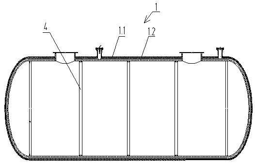
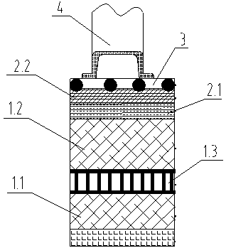
[0040] see Figure 1~5 , the present invention relates to a FF oil tank and its production process, the oil tank includes a tank body 1, the tank body 1 includes an outer shell 1.1, and an inner shell 1.2 set in the outer shell 1.1, the A gap layer 1.3 is formed between the outer shell 1.1 and the inner shell 1.2, the inner wall of the inner shell 1.2 is provided with a first inner lining layer 2.1, and the first inner lining layer 2.1 is provided with a second inner lining layer 2.2, the second lining layer 2.2 is provided with a conductive layer 3;

[0041] The inner casing 1.2 includes an inner cylinder and seals arranged at both ends of the inner cylinder, the outer diameter of the seal is equal to the inner diameter of the inner cylinder, the seal is inserted into the inner cylinder, and the seal Positioning pins are driven into the connection with the inner cylinder;

[0042] Further, in order to improve the pressure bearing capacity of the oil tank, a reinforcing ring...


PUM


Abstract

The invention relates to an FF oil tank and a production process thereof. The oil tank comprises a tank body (1), wherein the tank body (1) comprises an outer housing (1.1) and an inner housing (1.2) which sleeves in the outer housing (1.1), a gap layer (1.3) is formed between the outer housing (1.1) and the inner housing (1.2), a first liner layer (2.1) is arranged on the inner wall of the inner housing (1.2), a second liner layer (2.2) is arranged on the first liner layer (2.1), and a conductive layer (3) is arranged on the second liner layer (2.2); the inner housing (1.2) comprises an inner barrel and closure heads which are arranged at two ends of the inner barrel, the outer diameter of the closure heads is equal to the inner diameter of the inner barrel, the closure heads are inserted into the inner barrel, and positioning dowels are driven in the connecting parts of the closure heads and the inner barrel. The invention relates to the FF oil tank and the production process thereof. The FF oil tank is light in weight, good in corrosion resistance and good in sealing effect.

Description

technical field [0001] The invention relates to an oil tank, in particular to a double-layer FF oil tank made of double-layer glass fiber reinforced plastics and a new production process of the oil tank, belonging to the technical field of oil tanks. Background technique [0002] At present, the general oil tank adopts a double-layer structure, the inner shell is made of steel, and the outer shell is an insulating and anti-corrosion layer. The two layers are connected and supported by 3D structural materials, and the 3D structural material layer can be Use a leak detector for leak detection; [0003] However, in actual use, it is found that the above-mentioned structure has the following disadvantages: ①Because the material of the inner shell is steel, the entire oil tank is not only heavy, which affects handling and installation, but also has poor corrosion resistance (this is because in In an ultra-low sulfur environment, some microorganisms grow rapidly and produce aceti...

Claims


Application Information

Patent Timeline
Patent Type & Authority Patents(China)
IPC IPC(8): B65D90/02B65D90/04B65D90/10B65D90/08
CPCB65D90/028B65D90/041B65D90/08B65D90/10
Inventor 袁君伟周振华朱明国黄瑞娟俞飞鹏徐兴宝
Owner JIANGYIN FUREN HIGH TECH
Why Eureka
Try Eureka