Low nitrogen combustion device and low nitrogen combustion method

A low-nitrogen combustion and ignition device technology, applied in the combustion method, burner, combustion type, etc., can solve the problems such as the inability to fundamentally suppress the synthesis of nitrogen oxides, the large area of ​​the natural gas dilution pipeline, and the small flow of combustion-supporting air. Simple structure, compact and reasonable overall structure, and the effect of reducing calorific value

Active Publication Date: 2018-12-14
王研
View PDF8 Cites 0 Cited by
  • Summary
  • Abstract
  • Description
  • Claims
  • Application Information

AI Technical Summary

Problems solved by technology

[0003] When using this method, although the generation of nitrogen oxides in the combustion device can be reduced to a certain extent, it cannot fundamentally inhibit the synthesis of nitrogen oxides
First of all, a part of the low-temperature flue gas is extracted and sent directly into the furnace. The flow rate of the combustion air in the furnace is small, and the problem of incomplete combustion will occur.
Secondly, the flue gas is directly mixed into the air, which requires a large amount of flue gas and a large area of ​​the natural gas dilution pipeline

Method used


Image

  • Low nitrogen combustion device and low nitrogen combustion method
  • Low nitrogen combustion device and low nitrogen combustion method
  • Low nitrogen combustion device and low nitrogen combustion method

Examples


no. 1 example

[0056] Figure 4 It is a structural schematic diagram showing the first embodiment of the natural gas nozzle in the low-nitrogen combustion device of the present invention. Figure 5 It is a left view showing the structural schematic diagram of the first embodiment of the natural gas nozzle in the low-nitrogen combustion device of the present invention.

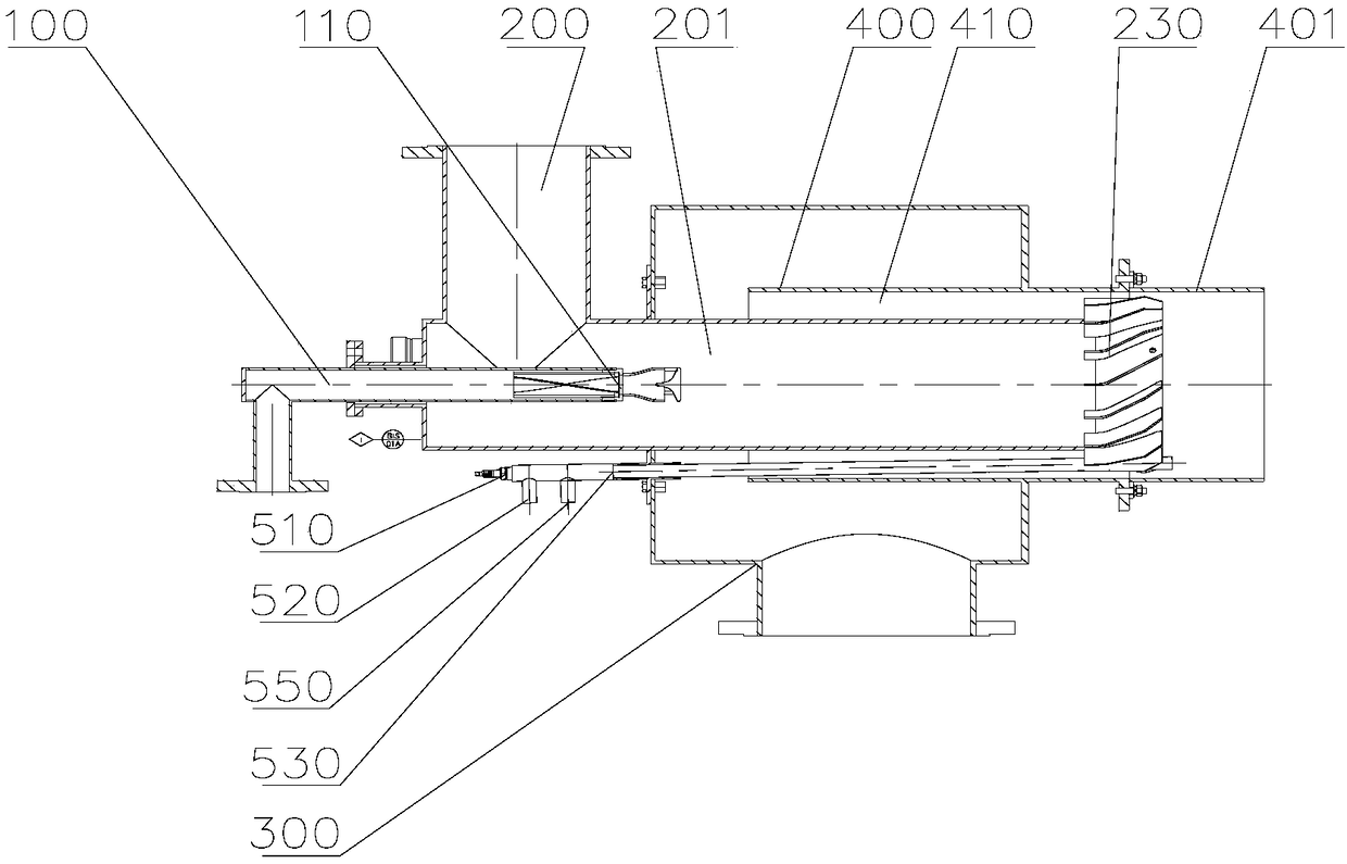
[0057] Such as Figure 4 with Figure 5 As shown, the natural gas nozzle 110 is formed by the front end of the natural gas pipe 100 , and the natural gas nozzle 110 is provided with a twist plate 111 at the center of the outlet end of the natural gas pipe 100 . After the natural gas is ejected through the twist plate 111 , it enters the natural gas dilution pipe 201 in a vortex shape, pushing the flue gas in the natural gas dilution pipe 201 forward, and mixes with the flue gas at the outlet end of the natural gas dilution pipe 201 .

no. 2 example

[0059] Image 6 It is a structural schematic diagram showing the second embodiment of the natural gas nozzle in the low-nitrogen combustion device of the present invention.

[0060] Such as Image 6 As shown, the natural gas spray head 110 is formed by the front end of the natural gas pipe 100 , and a flow guide pipe 112 and a flow guide cover 113 are installed at the outlet end of the natural gas spray head 110 .

[0061] Specifically, a twist plate 111 is arranged in the natural gas spray head 110 and is located at the center of the outlet end of the natural gas pipe 100 . On this basis, a flow guide pipe 112 and a conical flow guide cover 113 are added at the outlet end of the natural gas spray head 110 . After the natural gas passes through the twist plate 111, it is in a vortex shape, and the vortex-shaped natural gas enters the arc-shaped shroud 113 through the outlet of the guide tube 112, so that the natural gas diffuses into the natural gas dilution pipe 201 along t...

no. 3 example

[0063] Figure 7 It is a structural schematic diagram showing the third embodiment of the natural gas nozzle in the low-nitrogen combustion device of the present invention. Figure 8 It is a cross-sectional view of A-A showing the structure diagram of the third embodiment of the natural gas nozzle in the low-nitrogen combustion device of the present invention.

[0064] Such as Figure 7 with Figure 8 As shown, the natural gas nozzle 110 is formed by the front end of the natural gas pipe 100 , and a plurality of circular through holes with the same radius are formed on the pipe wall of the natural gas nozzle 110 . The natural gas enters the natural gas dilution pipe 201 through the through hole on the natural gas nozzle 110 , pushes the flue gas in the natural gas dilution pipe 201 forward, and mixes with the flue gas at the outlet end of the natural gas dilution pipe 201 .


PUM


Abstract

The invention relates to equipment for low-nitrogen combustion and a method for low-nitrogen combustion. The equipment for low-nitrogen combustion comprises a device for ignition, a device for flame detection, a natural gas pipeline, a flue gas pipe, a dilution pipe for natural gas, a combustion air room, and a guiding pipe for combustion air which is inserted into and connected with the combustion air room and a fire spraying pipe. The exit end of the natural gas pipeline is inserted inside the dilution pipe for natural gas from the entry end of the dilution pipe for natural gas. The flue gas pipe connects with the dilution pipe for natural gas through inner walls of the dilution pipe for natural gas, and the exit end of the dilution pipe for natural gas is inserted into the combustion air room and further inserted inside the guiding pipe for combustion air from the entry end of the guiding pipe for combustion air inside the combustion air room. The equipment for low-nitrogen combustion adopts a way of mixing natural gas with flue gas and blending the two gases inside the dilution pipe for natural gas in order to dilute the natural gas, thereby lowering calorific value of the natural gas, reducing the flame temperature, lowering the synthesis of nitric oxide fundamentally and realizing the effect of low-nitrogen combustion.

Description

technical field [0001] The invention relates to a low-nitrogen combustion device and a low-nitrogen combustion method. Background technique [0002] At present, most combustion devices and combustion methods use the flue gas recirculation method to recycle the flue gas. Usually, a part of the low-temperature flue gas is extracted and sent directly into the furnace, or mixed with primary air or secondary air and then sent into the furnace. For example, in a boiler that uses natural gas as fuel, the flue gas released from the boiler is directly mixed with air to reduce the density of oxygen in the combustion-supporting air, and the mixed gas is used as a combustion-supporting gas to mix with natural gas in the boiler, thereby burning natural gas. [0003] When this method is used, although the generation of nitrogen oxides in the combustion device can be reduced to a certain extent, it cannot fundamentally inhibit the synthesis of nitrogen oxides. First of all, a part of the ...

Claims


Application Information

Patent Timeline
Patent Type & Authority Patents(China)
IPC IPC(8): F23D14/00F23D14/46F23D14/58F23D14/60F23D14/70F23C9/06
CPCF23C9/06F23D14/00F23D14/46F23D14/58F23D14/60F23D14/70
Inventor 王研梁茜
Owner 王研
Why Eureka
Try Eureka