Ozone concentration measuring device

A technology for measuring device and ozone concentration, which is applied in the direction of measuring device, color/spectral characteristic measurement, material analysis through optical means, etc. It can solve the problems of increasing the average time of data processing, poor air chamber anti-pollution ability, energy attenuation, etc. Achieve the effects of improving the ability to resist stray light, improve the ability to resist pollution, and improve stability

Inactive Publication Date: 2017-01-04
QINGDAO HAINA PHOTOELECTRICAL ENVIRONMENTAL PROTECTION
View PDF9 Cites 7 Cited by
  • Summary
  • Abstract
  • Description
  • Claims
  • Application Information

AI Technical Summary

Problems solved by technology

[0005] (1) Using a low-pressure mercury lamp as a light source requires a long warm-up and stabilization time, and requires a start-up voltage of thousands of volts. The light source emits light to the surroundings, making the energy utilization rate low, and the light energy will attenuate with the prolongation of the use time, affecting equipment life
[0006] (2) The light beam emitted by the light source directly enters the glass tube gas chamber through the quartz window. In this way, the light beam enters the gas chamber freely, and only a small amount of light directly reaches the detector. Most of the light will be reflected on the gas chamber wall, which will The optical path of the beam passing through the gas chamber is not uniform, resulting in deviation of the measurement results
[0007] (3) The anti-pollution ability of the gas chamber is poor. When the front-end pretreatment part does not treat the measured gas thoroughly, moisture or particles are deposited on the gas chamber wall, causing changes in the reflection characteristics of the gas chamber wall, which will greatly affect the measurement results
[0008] (4) The photodetector directly detects the light beam passing through the gas chamber and through the quartz window. This detection method will be interfered by stray light, which will reduce the signal-to-noise ratio of the detection.
[0009] (5) An ultraviolet interference filter needs to be added in front of the photodetector. The low transmittance of the filter will cause a great attenuation of light energy and reduce the signal-to-noise ratio.
[0011] (1) The low-pressure mercury lamp 11 requires a relatively high starting voltage (thousands of volts), which requires a high driving circuit; the stabilization time is long, and tens of minutes of preheating is required to stabilize; the light beam 12 diverges, and the energy utilization rate is low; As the use time increases, the energy will decay at an accelerated rate, resulting in a decrease in stability, requiring frequent calibration
[0012] (2) The front quartz window 13 is a flat glass plate, which only plays the role of light transmission and sealing. The light beam is in a state of free propagation in the gas chamber, and multiple reflections will occur on the wall of the gas chamber. The state of the light beam at different incident angles Inconsistency, resulting in inconsistency in the optical path of each beam of light
[0013] (3) Since a large proportion of the light beam will be reflected on the inner wall of the glass tube air chamber 14, if there is water vapor or particle pollution on the air chamber wall, it will cause a large reflection attenuation, resulting in instability of the measurement signal
[0014] (4) The back-end quartz window 15 also only plays a light-transmitting and sealing effect, does not contribute to the adjustment of the light beam, and the light beam with a larger exit angle will not reach the ultraviolet photodetector 17
[0015] (5) Since the low-pressure mercury lamp 11 has many spectral lines with multiple wavelengths, it is necessary to add a narrow-band filter 16 to allow only 254nm light to pass through. Generally, the transmittance of the narrow-band interference filter is relatively low, only about 20%. , so the narrow-band filter will greatly reduce the energy
The above-mentioned existing solutions result in low light energy utilization rate and large stray light. In order to improve the detection capability, the method adopted is to increase the power of the light source, increase the length of the gas chamber, and increase the average time of data processing, which will cause large equipment volume and low power consumption. high, slow response
[0016] The above problems limit the detection ability of the existing ultraviolet photometer, and it is necessary to use a larger light source power, a longer gas chamber optical path and a larger volume to make up for the above defects, thereby improving the ozone detection ability, which is also the cause of the existing equipment. The main reasons for large volume, high power consumption and slow response

Method used


Image

  • Ozone concentration measuring device
  • Ozone concentration measuring device
  • Ozone concentration measuring device

Examples


Embodiment Construction

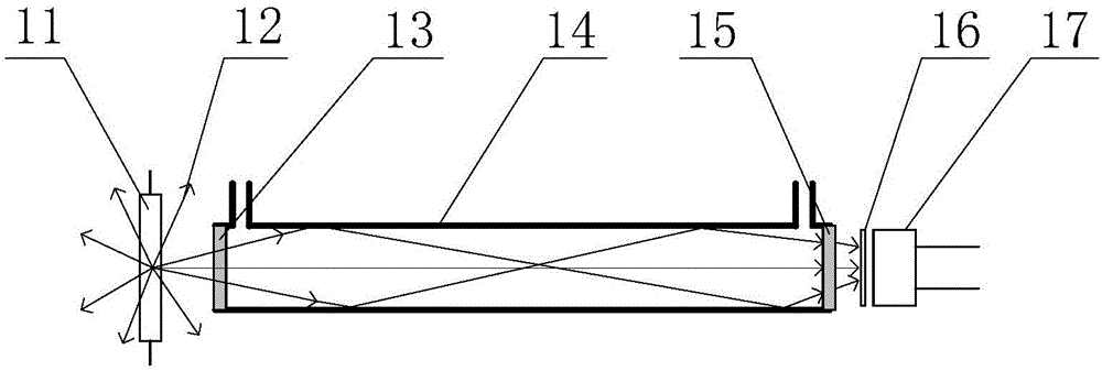
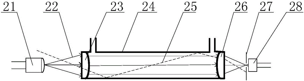
[0036] like Figure 2-5 As shown, the present invention provides a kind of ozone concentration measuring device, comprises ultraviolet light emitting device, gas chamber to be tested, ultraviolet light detection device, wherein the ultraviolet light that said ultraviolet light emitting device sends is injected into the described gas chamber to be measured The incident port, the outgoing light of the exit port of the gas chamber to be tested is converged and irradiated onto the ultraviolet light detection device, and a stray light elimination device is arranged on the front optical path of the ultraviolet light detection device, and the stray light elimination device The center of the device has a light-transmitting hole, and the light-transmitting hole is arranged on the main optical axis.

[0037] Wherein, the ultraviolet light detection device is an ultraviolet photodetector, and the ultraviolet photodetector can be a photodetector with good spectral response in the emission...


PUM

PropertyMeasurementUnit
wavelengthaaaaaaaaaa

Abstract

An ozone concentration measuring device comprises an ultraviolet emitting device, a to-be-measured gas chamber and an ultraviolet detecting device. Ultraviolet emitted by the ultraviolet emitting device irradiates into an incidence port of the to-be-measured gas chamber, emergent light from an emergent port of the to-be-measured gas chamber irradiates on the ultraviolet detecting device after converging, a stray light eliminating device is arranged on a front-end light path of the ultraviolet detecting device, a light transmitting hole is formed in the center of the stray light eliminating device, and the light transmitting hole is formed in a main light shaft. By the ozone concentration measuring device, the problems of long light source stabilizing time, high starting voltage, low light energy utilization rate and quick light energy attenuation of the prior art are solved, light path stability of the gas chamber is improved, anti-pollution capability is improved, and resistance to stray light is improved.

Description

technical field [0001] The invention relates to the field of ozone concentration detection equipment, in particular to an ozone concentration measurement device, in particular to an ultraviolet photometer for detecting ozone concentration. Background technique [0002] Ozone is a trace gas with active chemical properties in the atmosphere. It has strong oxidizing properties, greenhouse effect and ultraviolet absorption characteristics. It has important significance and influence on climate, ecology and environment. Ozone is also one of the most important secondary pollutants in urban ambient air. It is one of the main causes of pollution phenomena such as acid rain, photochemical smog, and reduced atmospheric visibility, and it can also cause serious harm to the human body. Ozone has become a must-test item for air quality monitoring in developed countries. In recent years, ozone has also become the primary pollutant in some cities in China, and the monitoring of ozone has ...

Claims


Application Information

Patent Timeline
Patent Type & Authority Applications(China)
IPC IPC(8): G01N21/33G01N21/01
CPCG01N21/01G01N21/33G01N2201/0612G01N2201/064G01N2201/068
Inventor 王新全武婧徐少才梁永
Owner QINGDAO HAINA PHOTOELECTRICAL ENVIRONMENTAL PROTECTION
Why Eureka
Try Eureka