Small sized navigation reception antenna

An antenna unit and grounding plate technology, applied in the field of satellite navigation signal reception, can solve the problems of unable to meet the system use requirements, stay in the research and simulation stage, reduce the working bandwidth of the antenna, etc., and achieve light weight, compact structure and small size. Effect

Inactive Publication Date: 2017-01-04
NO 20 RES INST OF CHINA ELECTRONICS TECH GRP
View PDF4 Cites 14 Cited by
  • Summary
  • Abstract
  • Description
  • Claims
  • Application Information

AI Technical Summary

Problems solved by technology

Increasing the dielectric constant of the dielectric substrate can reduce the dielectric wavelength of the microstrip antenna and achieve the purpose of reducing the size of the radiation patch, but a higher dielectric constant will increase the loss of the dielectric plate to a certain extent, reduce the gain of the antenna, and reduce the radiation efficiency ; while slotting on the surface of the radiation patch can increase the path of the surface current to reduce the size of the patch, but at the same time it will reduce the working bandwidth of the antenna, which cannot meet the requirements of the system
[0004] Scholars at home and abroad have also proposed loading short-circuit probe loading, capacitive inductance loading and other methods, but they are still in the research and simulation stage, and have not realized engineering

Method used


Image

  • Small sized navigation reception antenna
  • Small sized navigation reception antenna
  • Small sized navigation reception antenna

Examples


Embodiment Construction

[0024] The present invention will be further described below in conjunction with the accompanying drawings and embodiments, and the present invention includes but not limited to the following embodiments.

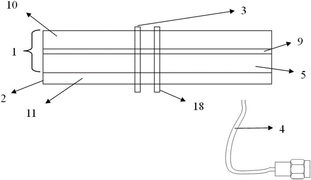
[0025] The invention includes an antenna unit, a feeding board, a feeding probe, a grounding probe and a radio frequency cable.

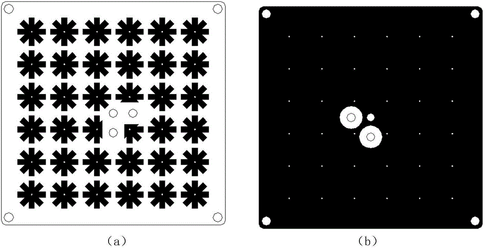
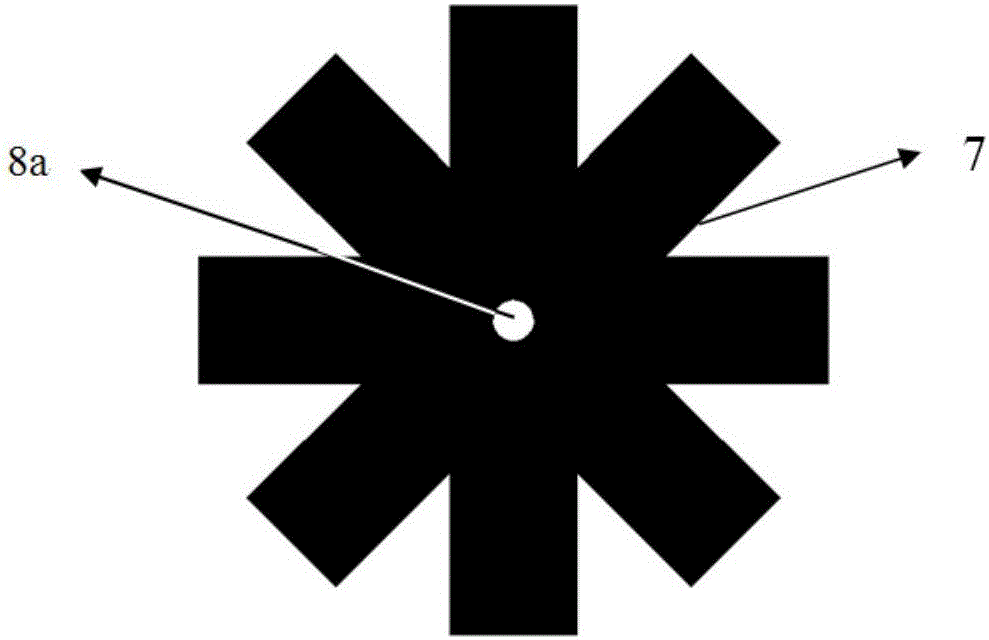
[0026] The antenna unit includes a bottom dielectric substrate, a middle prepreg, and a top dielectric substrate. The bottom dielectric substrate is a double-sided copper-clad plate, including an upper layer electromagnetic bandgap structure array, a middle dielectric substrate and a lower ground plane. The upper electromagnetic bandgap structure array is composed of 36 "meter"-shaped metal patch units, each metal patch unit is connected to the lower ground plate through a conductive metallized through hole, arranged in a 6×6 array . In order to avoid the three through holes in the middle of the substrate, the several "meter"-shaped patches in ...


PUM


Abstract

The invention provides a small sized navigation reception antenna comprising an antenna unit, a feeding plate, feeding probes, a grounding probe and an RF cable. The antenna unit comprises a bottom dielectric substrate, a middle prepreg and a top layer dielectric substrate which are closely arranged in sequence. The bottom dielectric substrate is a double-sided copper-clad board, and the upper electromagnetic band-gap structure array comprises a plurality of metal patches arranged in an array. The top dielectric substrate is a one-sided copper clad plate, and the upper layer mounted radiation patch is composed of a central main radiation patch and four parasitic radiation patches on the edge. The feeding plate is located below the antenna unit, and the two are welded together by means of two feeding probes and five grounding probes. The antenna of the invention has a reduced size without compromising the gain and the bandwidth, and can fully meet the requirements of various kinds of satellite guidance terminals.

Description

technical field [0001] The invention relates to a miniaturized double-feed point circularly polarized microstrip antenna for satellite navigation signal reception. Background technique [0002] With the continuous development of satellite navigation technology, various mobile and portable satellite navigation terminals have sprung up, and the satellite navigation receiving antenna, as a front-end component of communication equipment, plays a vital role in communication quality. With the development of the modern satellite communication market, the demand for miniaturized and highly stable terminal products is increasing, leaving little space for antenna layout, which requires the size of the front-end receiving antenna to be reduced as much as possible. [0003] Usually, the receiving antenna of satellite navigation terminal adopts the basic form of microstrip antenna, which has the advantages of low profile, easy conformal shape, simple structure and easy realization. At p...

Claims


Application Information

Patent Timeline
Patent Type & Authority Applications(China)
IPC IPC(8): H01Q1/38H01Q1/50
CPCH01Q1/38H01Q1/50
Inventor 张海光张佳许奎梁西铭李明尤浩张骅郭卫展
Owner NO 20 RES INST OF CHINA ELECTRONICS TECH GRP
Why Eureka
Try Eureka