Thermoacoustic heat regenerator based on surface acoustic wave generator

A surface acoustic wave and regenerator technology, which is applied to superheaters, mechanical power generating mechanisms, refrigeration components, etc., can solve the problems of low thermoacoustic conversion efficiency, achieve enhanced heat transfer, stabilize acoustic power output, and improve acoustic performance. The effect of power output

Inactive Publication Date: 2017-01-18
CENT SOUTH UNIV
View PDF8 Cites 2 Cited by
  • Summary
  • Abstract
  • Description
  • Claims
  • Application Information

AI Technical Summary

Problems solved by technology

[0009] The technical problem to be solved in the present invention is: aiming at the problem of low thermoacoustic conversion efficiency of ordinary plate-stacked regenerators, the surface acoustic wave is applied to the ordinary plate-stacked regenerator, and the surface acoustic wave device is etched on the The surface of the plate stack is designed to be a new type of thermoacoustic regenerator that can improve the thermoacoustic conversion efficiency, expand the application field of the thermoacoustic regenerator, and improve the overall efficiency of the thermoacoustic heat engine and the cryogenic refrigerator.

Method used


Image

  • Thermoacoustic heat regenerator based on surface acoustic wave generator
  • Thermoacoustic heat regenerator based on surface acoustic wave generator
  • Thermoacoustic heat regenerator based on surface acoustic wave generator

Examples


specific Embodiment 1

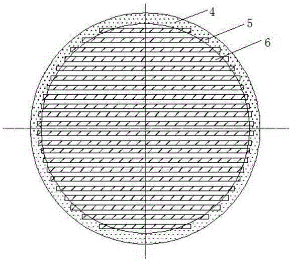
[0051] The present invention adopts the welding method to manufacture the plate stack, and grooves the inner wall of the metal sleeve of the regenerator, the groove width is the same as the thickness of the plate stack, and then cuts the produced regenerator plate stack to the same size as the groove of the sleeve. The corresponding small plates are stacked, and then assembled and combined. The thickness of the material, the width b of the material itself is 100mm, and the length a of the base material is 1000mm.

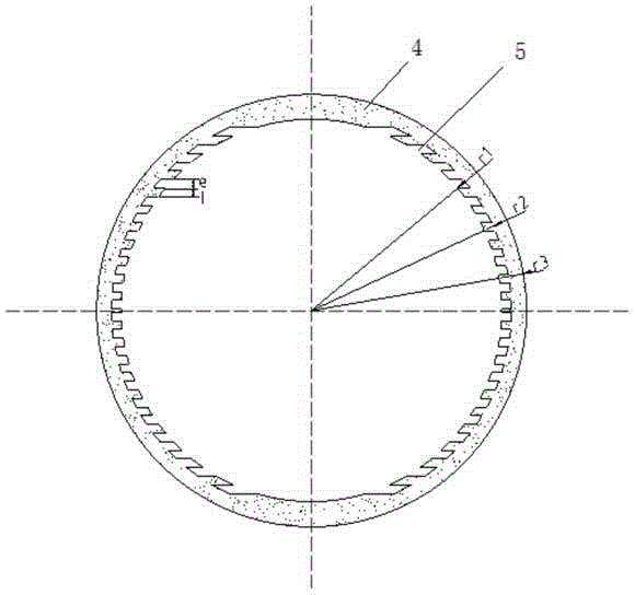
[0052] The sleeve material is made of stainless steel, the inner radius r1 of the sleeve is 50mm, the outer radius r3 is 54mm, and the thickness of the sleeve is 4mm. The inner wall of the sleeve is grooved, the groove width e is 2mm the same as the thickness e of the regenerator plate stack installed, the plate spacing is 2mm, and the groove depth is half the thickness of the sleeve pipe wall, that is, the groove depth radius r2 after groove is 52mm, Length 1000mm...

specific Embodiment 2

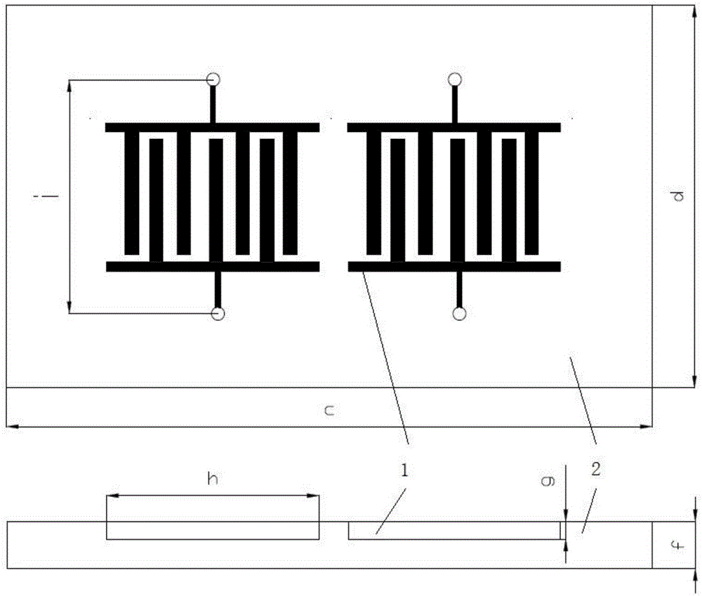
[0054] The piezoelectric film substrate is made of lead zirconium titanium acid series (PZT) material. The length c of a single piece of material is 25mm, and the width d is 10mm. Film thickness.

specific Embodiment 3

[0056] The thickness g of the interdigital transducer is 0.25 microns, and the length h and width i are both 1.2 microns. The electrode width of the 201 pair of electrodes is 0.25 times the wavelength of the sound wave, and the finger spacing is 0.5 times the wavelength of the sound wave. Using electron beam evaporation and stripping technology, the width of the electron beam is 30 times the wavelength of the sound wave. At 200 degrees Celsius, a voltage of 20V is applied to polarize the piezoelectric material.


PUM


Abstract

The invention relates to a novel thermoacoustic heat regenerator capable of improving thermoacoustic heat regenerator heat regenerating and thermoacoustic transition efficiency; the novel thermoacoustic heat regenerator can supplement partial viscosity loss energy in the heat regenerator heat exchange process, and can use oscillations formed by surface acoustic waves to convert nature convection on a stack surface into forced convection, thus enhancing heat exchange capability, and improving efficiency; the thermoacoustic heat regenerator comprises a stacked structure heat regenerator and a surface acoustic wave generator, wherein the stacked structure is formed by combining a pres-stamping forming thin plate with a heat regenerator sleeve; the surface acoustic wave generator is formed by using an electron beam to etch a PZT piezoelectric material; the novel thermoacoustic heat regenerator fully uses the thermoacoustic transition principle, and employs the mature technology, simple structure and low cost features of the stack heat regenerator, thus solving the problems that a conventional heat regenerator is large in viscosity dissipation, not obvious in heat exchange, and poor in efficiency; the novel thermoacoustic heat regenerator has excellent application values.

Description

technical field [0001] The present invention relates to a new type of thermoacoustic regenerator, in particular, it relates to a regenerating and thermoacoustic conversion efficiency, which is convenient for processing, installation and debugging, and can be widely used in thermoacoustic heat engines and cryogenic refrigerators. New thermoacoustic regenerator. Background technique [0002] Thermoacoustic refrigeration technology is a completely new type of refrigeration technology, which is a refrigeration technology that utilizes the thermoacoustic effect. The thermoacoustic effect is the mutual transformation between heat and sound. From an acoustic point of view, it is the interaction between the solid medium in the sound field and the oscillating fluid, which makes the heat flow along (or against) the direction of sound propagation within a certain range from the solid boundary, and generates or The phenomenon of absorbing sound power. According to the direction of en...

Claims


Application Information

Patent Timeline
Patent Type & Authority Applications(China)
IPC IPC(8): F25B40/06F03G7/00
Inventor 刘益才武曈方莹雷斌义
Owner CENT SOUTH UNIV
Why Eureka
Try Eureka