
Energy-saving and emission-reduction tunnel kiln suitable for firing of ceramic products

A technology of energy saving and emission reduction and tunnel kiln, which is applied in the production of ceramic materials, furnace types, furnaces, etc., can solve the problems of unsatisfactory reflow application of waste heat reuse, uneven cross-section temperature, low energy utilization rate, etc., and achieve improvement The effect of energy saving and emission reduction, temperature stability and uniformity, and the effect of improving energy utilization rate

Inactive Publication Date: 2017-01-18
广东明宇科技股份有限公司
View PDF7 Cites 2 Cited by
  • Summary
  • Abstract
  • Description
  • Claims
  • Application Information

AI Technical Summary

Problems solved by technology

[0002] Tunnel kiln is a modern thermal equipment for continuous firing. It is generally a long linear tunnel with three zones, namely preheating zone, firing zone and cooling zone. Both sides are insulation walls and the top is It is a vaulted roof, and tracks are laid in the tunnel to run the kiln car. Since the heat will flow in different temperature ranges during use, the energy utilization rate is low. In this regard, there are also learning to set up fire-retaining walls in the firing zone to separate high-temperature areas. To prevent heat loss, but it is not conducive to the passage of kiln cars
It is found that the control of each temperature zone in the tunnel is relatively simple in the existing technology, especially in the high temperature zone, it is easy to cause uneven cross-section temperature and cause product cracking. In addition, the reflux application of waste heat reuse is not satisfactory, which is not conducive to energy saving emission reduction

Method used


Image

  • Energy-saving and emission-reduction tunnel kiln suitable for firing of ceramic products
  • Energy-saving and emission-reduction tunnel kiln suitable for firing of ceramic products
  • Energy-saving and emission-reduction tunnel kiln suitable for firing of ceramic products

Examples


Embodiment Construction

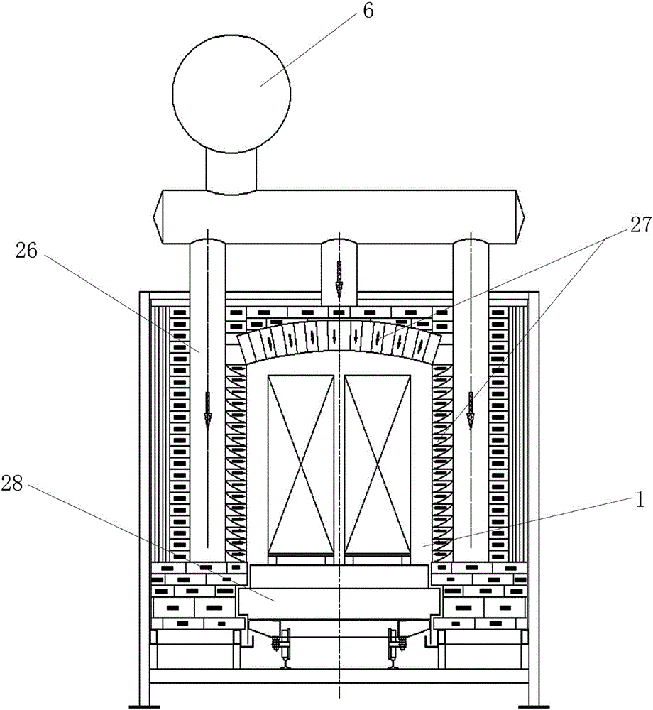
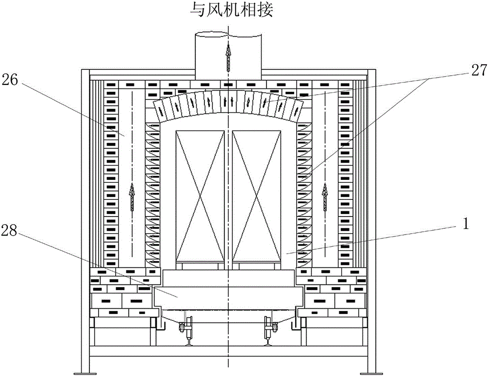
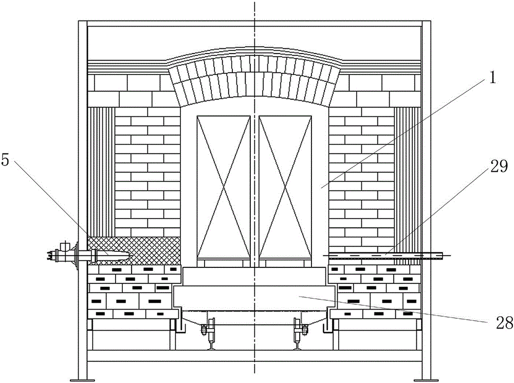
[0036] As shown in the figure, an energy-saving and emission-reducing tunnel kiln suitable for firing ceramic products includes a kiln body channel, a fan system, and a combustion system. A kiln car 28 is installed or loaded with ceramic embryo products and moved in the kiln body channel 1 . The kiln channel 1 has a total length of 82 meters and is divided into six sections, which are respectively an oxidation evaporation section 20, a strong oxidation section 21, a strong reduction section 22, a firing section 23, a heat preservation section 24, and a cooling section 25, wherein the oxidation evaporation section Area 20 is the drying zone 12, and the drying zone 12 is 0-15 meters of the kiln body channel, with a length of 15 meters. Air ducts are respectively provided at the 2nd, 4th and 10th meters of the entrance of the kiln body channel. 2 and the 10th meter are connected to the inlet smoke exhaust fan 2 through the air duct to exhaust outwards (such as image 3 As shown),...


PUM


Abstract

The invention relates to an energy-saving and emission-reduction tunnel kiln suitable for firing of ceramic products. The energy-saving and emission-reduction tunnel kiln suitable for firing of the ceramic products comprises a kiln body channel, a draught fan system and a combustion system. A kiln body is arranged in the kiln channel. The kiln channel is provided with an oxidation evaporation section, a strong oxidation section, a strong reduction section, a firing section, a heat preservation section and a cooling section. The draught fan system is composed of an inlet smoke exhaust draught fan, an air curtain conversion draught fan, a chilling draught fan, a heat extraction draught fan, a combustion-supporting draught fan, a kiln tail air supply draught fan, air channels and a vent duct. Each air channel comprises a cavity layer arranged on the wall of the kiln body, and the cavity layers communicate with air outlets formed in the wall of the kiln body and in a vault of the kiln body. The combustion system is composed of a gas inlet pipe and flame guns. The combustion-supporting draught fan provides combustion-supporting air to the flame guns. The energy-saving and emission-reduction tunnel kiln suitable for firing of the ceramic products has a high energy utilization rate and the remarkable technological advantages of energy saving and emission reduction and achieves the effect that the overall energy can be saved by 30%; and the temperature in a high-temperature area is stable and uniform, and therefore firing of the products is facilitated.

Description

technical field [0001] The invention relates to firing thermal equipment in the field of ceramics, in particular to an energy-saving and emission-reducing tunnel kiln suitable for firing ceramic products. Background technique [0002] Tunnel kiln is a modern thermal equipment for continuous firing. It is generally a long linear tunnel with three zones, namely preheating zone, firing zone and cooling zone. Both sides are insulation walls and the top is It is a vaulted roof, and tracks are laid in the tunnel to run the kiln car. Since the heat will flow in different temperature ranges during use, the energy utilization rate is low. In this regard, there are also learning to set up fire-retaining walls in the firing zone to separate high-temperature areas. In order to prevent heat loss, but it is not conducive to the passage of kiln cars. It is found that the control of each temperature zone in the tunnel is relatively simple in the existing technology, especially in the high ...

Claims


Application Information

Patent Timeline
Patent Type & Authority Applications(China)
IPC IPC(8): F27B9/04F27B9/12F27B9/30F27B9/36
CPCY02P40/60
Inventor 邱秋雄
Owner 广东明宇科技股份有限公司
Learn More