Energy-uniformly-distributed ultrasonic/megasonic cleaning device

A technology for uniform energy and cleaning devices, which is applied in the fields of cleaning methods using liquids, cleaning methods and appliances, semiconductor/solid-state device manufacturing, etc., which can solve the problem of poor compensation effects, high requirements for piezoelectric materials, and the inability to achieve fine Control and other issues to achieve uniform energy distribution and improve uniformity

Active Publication Date: 2017-01-18
BEIJING SEVENSTAR ELECTRONICS CO LTD
View PDF5 Cites 11 Cited by
  • Summary
  • Abstract
  • Description
  • Claims
  • Application Information

AI Technical Summary

Problems solved by technology

[0009] However, the above two methods have their own problems. The method (1) has high requirements for the production of piezoelectric materials. For 300mm wafers and 450mm wafers to be adopted in the future, fan-shaped piezoelectric materials covering from the center of the wafer to the edge Multiple pieces of piezoelectric materials need to be spliced ​​together, and these piezoelectric materials need to have exactly the same natural frequency, which greatly increases the difficulty and cost of manufacturing the transducer of the cleaning device
In method (2), since the motion speed control of the spray arm is performed by the motor, fine regulation cannot be achieved, resulting in poor compensation for the difference in linear speed at different positions

Method used


Image

  • Energy-uniformly-distributed ultrasonic/megasonic cleaning device
  • Energy-uniformly-distributed ultrasonic/megasonic cleaning device
  • Energy-uniformly-distributed ultrasonic/megasonic cleaning device

Examples


Embodiment Construction

[0056] The specific embodiment of the present invention will be further described in detail below in conjunction with the accompanying drawings.

[0057] It should be noted that, in the following specific embodiments, when describing the embodiments of the present invention in detail, in order to clearly show the structure of the present invention for the convenience of description, the structures in the drawings are not drawn according to the general scale, and are drawn Partial magnification, deformation and simplification are included, therefore, it should be avoided to be interpreted as a limitation of the present invention.

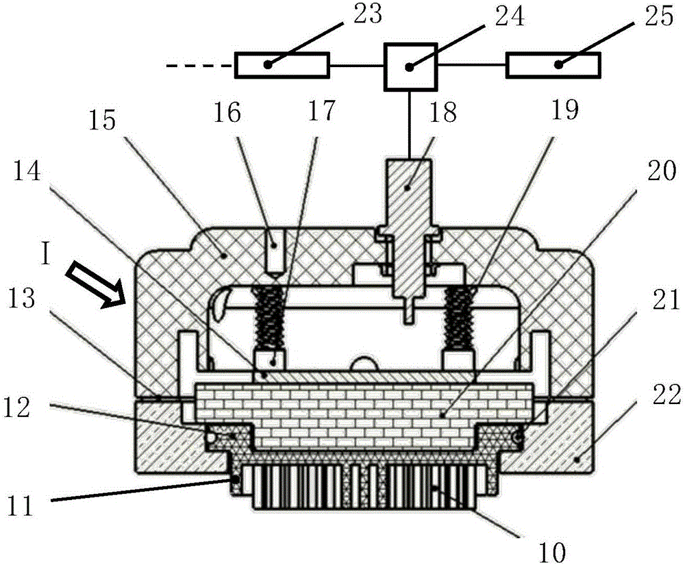
[0058] In the following specific embodiments of the present invention, first please refer to figure 1 , figure 1 It is a structural schematic diagram of an ultrasonic / megasonic cleaning device with uniform energy distribution in an embodiment of the present invention. Such as figure 1 As shown, an ultrasonic / megasonic cleaning device with uniform ...


PUM


Abstract

The invention discloses an energy-uniformly-distributed ultrasonic / megasonic cleaning device. A body is internally provided with an ultrasonic / megasonic generation mechanism and a bottom quartz component. The ultrasonic / megasonic generation mechanism is provided with a piezoelectric material. The bottom quartz component is provided with a quartz micro resonant cavity array. The quartz micro resonant cavity array extends from an opening in the lower end surface of the body; the ultrasonic / megasonic energy, the propagation direction of which is not vertical to the wafer surface direction, can be removed selectively through the quartz micro resonant cavity array; the output electrical signals of a signal source are adjusted through an ultrasonic / megasonic energy control unit according to relative position information of the body on the wafer surface collected by a real-time position feedback unit from a spray rotary motor; and after conversion through the piezoelectric material, any position of the surface of a wafer is allowed to obtain the same ultrasonic / megasonic energy within unit time, thereby realizing uniform distribution of the ultrasonic / megasonic energy in the whole wafer range.

Description

technical field [0001] The invention relates to the field of processing and cleaning equipment for semiconductor integrated circuits, and more particularly relates to an ultrasonic / megasonic cleaning device that realizes uniform and non-damaging cleaning of patterned wafers by dynamically changing the energy of ultrasonic / megasonic waves. Background technique [0002] With the rapid development of semiconductor integrated circuit manufacturing technology, the graphic feature size of integrated circuit chips has entered the deep sub-micron stage, and the feature size of key contaminants (such as particles) that cause failure or damage to ultra-fine circuits on the chip has also changed. greatly reduced. [0003] During the production and processing process of integrated circuits, semiconductor wafers usually go through multiple process steps such as film deposition, etching, and polishing. And these process steps just become the important place that the contamination produce...

Claims


Application Information

Patent Timeline
Patent Type & Authority Applications(China)
IPC IPC(8): H01L21/67H01L21/02B08B3/12
Inventor 滕宇吴仪
Owner BEIJING SEVENSTAR ELECTRONICS CO LTD
Why Eureka
Try Eureka