Device and method for removing sulfur trioxide from coal-fired flue gas
A technology for sulfur trioxide and coal-fired flue gas, which is applied in chemical instruments and methods, separation methods, gas treatment and other directions to achieve the effects of reducing hazards, ultra-low emissions, and realizing ultra-low emissions
- Summary
- Abstract
- Description
- Claims
- Application Information
AI Technical Summary
Problems solved by technology
Method used
Image
Examples
Embodiment 1
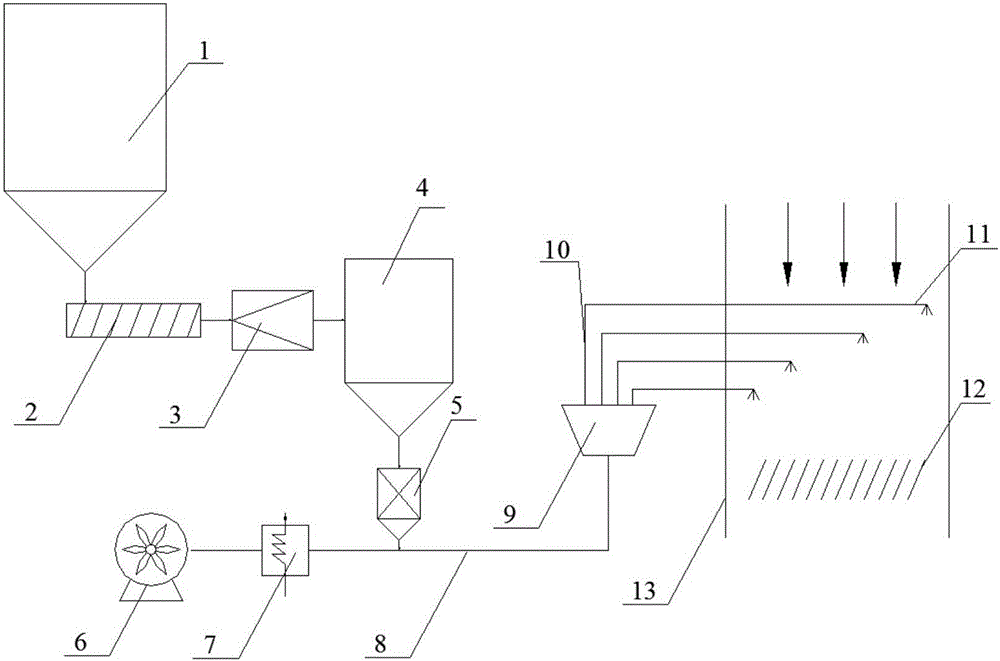
[0040] refer to figure 1 , a coal-fired flue gas sulfur trioxide removal device, including a flue 13, the device also includes a coarse material bin 1, a screw feeder 2, an air classification mill 3, and a fine material bin 4 connected in sequence , loss-in-weight feeder 5, main pipeline 8, separator 9 and spray gun 11, described spray gun 11 is arranged in the flue 13, is arranged with static mixer 12 in the downstream flue of spray gun 11; Described main pipeline 8 also passes The air dryer 7 communicates with the blower 6 .
[0041] The main pipeline 8 communicates with several pipeline branches 10 through a separator 9, and each pipeline branch communicates with a corresponding spray gun 11; the number of the pipeline branches is four. The fine material bin is a sealing device, and is equipped with a drying device to prevent the alkaline absorbent from agglomerating, scaling, and blocking the pipeline due to water absorption.
[0042] The location where the alkaline abso...
Embodiment 2
[0044] Removal of SO in flue before SCR 3 , the flue position is between the economizer and the SCR reactor. Flue gas temperature 400°C, SO 3 Concentration 25ppm. According to the flue gas conditions there, select trona (Na 2 CO 3 ·NaHCO 3 2H 2 O) as absorbent, trona and SO 3 The molar ratio is 2:1. The average particle size of the trona coarse material is 2mm, the average particle size of the fine material is determined to be 40μm, and the residence time of the alkaline absorbent in the flue is 2s.
[0045] Such as figure 1 As shown, when the system is running, a large amount of trona coarse material is stored in the coarse material bin 1, with an average particle size of 2 mm. The bottom of the coarse material bin 1 is connected with the screw feeder 2; the trona with coarse particles is sent to the air classification mill 3 by the screw feeder 2, and the trona is ground to an average particle size of 40 μm, and then sent into the fine material bin 4 The fine mater...
Embodiment 3
[0048] The difference between this embodiment and embodiment 2 is to remove the SO in the flue before the air preheater 3 , the flue position is between the SCR reactor and the air preheater. Flue gas temperature 250°C, SO 3 The concentration is 40ppm. According to the flue gas conditions there, choose Mg(OH) 2 As absorbent, Mg(OH) 2 with SO 3 The molar ratio is 4:1. Mg(OH) 2 The particle size of the coarse material is 3mm, the average particle size of the fine material is determined to be 60μm, and the residence time of the alkaline absorbent in the flue is 1s.
[0049] Under the design conditions, the SO can be guaranteed 3 The removal efficiency is 84%. Effectively prevent the clogging and corrosion of the air preheater.
PUM
 Abstract
Description
Claims
Application Information
 - R&D
- Intellectual Property
- Life Sciences
- Materials
- Tech Scout
- Unparalleled Data Quality
- Higher Quality Content
- 60% Fewer Hallucinations
Browse by: Latest US Patents, China's latest patents, Technical Efficacy Thesaurus, Application Domain, Technology Topic, Popular Technical Reports.
© 2025 PatSnap. All rights reserved.Legal|Privacy policy|Modern Slavery Act Transparency Statement|Sitemap|About US| Contact US: help@patsnap.com

