Robot welding motion control method based on laser seam tracking sensor

A robot welding and motion control technology, applied in laser welding equipment, welding equipment, manufacturing tools, etc., can solve the problems of inability to meet the requirements of industrial welding accuracy, lack of unknown welding trajectories, etc., to achieve fast execution efficiency, good versatility, High welding precision

Inactive Publication Date: 2017-01-25
CHINA JILIANG UNIV
View PDF10 Cites 17 Cited by
  • Summary
  • Abstract
  • Description
  • Claims
  • Application Information

AI Technical Summary

Problems solved by technology

This mode can no longer meet the precision requirements required by industrial welding, and does not have the ability to weld unknown trajectories

Method used


Image

  • Robot welding motion control method based on laser seam tracking sensor
  • Robot welding motion control method based on laser seam tracking sensor
  • Robot welding motion control method based on laser seam tracking sensor

Examples


Embodiment Construction

[0014] The present invention will be further described below in conjunction with the accompanying drawings and specific embodiments.

[0015] (1) Initial parameter setting of robot motion algorithm

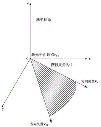
[0016] According to the robot kinematics theory, set the robot sensor world coordinate system {W}, and the robot end tool coordinate system {T}.

[0017] Robot world coordinate system {W}: the coordinate system O w -X w Y w Z w It is used to uniformly describe the pose and coordinates of various objects such as robots, welding torches, and welds.

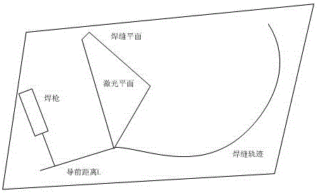
[0018] Robot end coordinate system {T}: the coordinate of welding torch vertex is P TT , the torch direction vector is V TT . Such as figure 1 As shown, the vertex of the laser triangle plane is P LT , the direction vectors of the two boundaries of the triangular plane are V 1T , V 2T . And set the welding speed as v, the motion period of the control system as t, and the leading distance between the sensor and the welding to...


PUM


Abstract

The invention discloses a robot welding motion control method based on a laser seam tracking sensor. The method includes the steps that the world coordinate system of an initial welding robot, a robot tail end tool coordinate system, the welding gun initial point, laser triangular plane parameters, welding speed and motion time are set first; then the welding gun top end position point in the next control period is searched for from data points in a centralized mode according to measurement data of the laser seam tracking sensor; finally the optimal posture of the welding gun is searched for through a genetic algorithm. The robot welding motion control method has the advantages of being high in welding accuracy, high in execution efficiency, high in generality and capable of being widely applied to welding of various space unknown straight line or curve welding seams.

Description

technical field [0001] The invention is based on a laser scanning seam tracking sensor, and according to the robot kinematics principle, intelligently controls the welding robot to track the seam trajectory for welding. Background technique [0002] Welding plays a very important role in industrial production. With the continuous improvement of the country's economic level, people put forward higher requirements for welding quality in production. In the existing automatic welding process, the robot often performs welding according to a fixed welding seam trajectory through a teaching method. This mode can no longer meet the precision requirements required by industrial welding, and does not have the ability to weld unknown trajectories. The weld seam detection sensor detects the position of the weld seam in real time and tracks and guides the robot to hold the welding torch to weld according to the actual trajectory of the detected weld seam, so that the apex of the weldin...

Claims


Application Information

Patent Timeline
Patent Type & Authority Applications(China)
IPC IPC(8): B23K26/044
CPCB23K26/044
Inventor 唐琛张斌
Owner CHINA JILIANG UNIV
Why Eureka
Try Eureka