
Micro wave high-frequency-band dual polarization small base station plate antenna

A flat-panel antenna and high-frequency band technology, which is applied in the direction of antenna coupling, antenna grounding switch structure connection, radiation element structure, etc., can solve the problems of limited array spacing, influence on antenna radiation characteristics, and large switching loss, etc., so as to facilitate mass production , good repeatability and low cost

Pending Publication Date: 2017-01-25
SOUTHEAST UNIV
View PDF6 Cites 8 Cited by
  • Summary
  • Abstract
  • Description
  • Claims
  • Application Information

AI Technical Summary

Problems solved by technology

[0005] 1. With the increase of operating frequency and the shortening of the corresponding operating wavelength (<3cm or mm order), the current commercial frequency band (below 3GHz) in the form of die-casting or metal plate-shaped antenna units will not be able to continue to be used, mainly because of The difficulty and error of processing and assembly will increase, thereby reducing the efficiency of the antenna;
[0006] 2. The traditional cable feeder network method will not continue to be used due to assembly errors and excessive transfer loss between cables and arrays;
However, due to the limited spacing between elements in the base station antenna, when the number of elements is large and the array is complex, the layout of the feeder will be greatly restricted.
Mutual coupling and crosstalk between feeders will greatly affect the radiation characteristics and polarization isolation characteristics of the antenna
At the same time, the inherent surface wave problem of the patch antenna will also affect the radiation characteristics of the antenna

Method used


Image

  • Micro wave high-frequency-band dual polarization small base station plate antenna
  • Micro wave high-frequency-band dual polarization small base station plate antenna
  • Micro wave high-frequency-band dual polarization small base station plate antenna

Examples


Embodiment 1

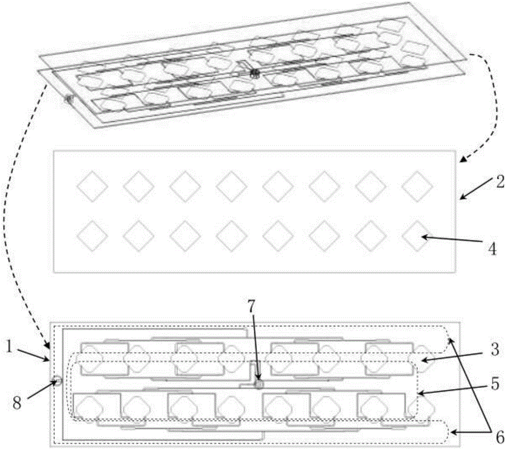
[0027] Embodiment 1: as figure 1As shown, a microwave high-frequency dual-polarization small base station panel antenna includes a lower dielectric substrate 1, an upper dielectric substrate 2, and a 45-degree cut pattern printed on the front of the lower dielectric substrate 1 arranged in two rows and eight columns. Angular square main radiating metal patches 3, square parasitic radiating metal patches 4 arranged in two rows and eight columns rotated by 45°, printed on the lower surface of the upper dielectric substrate 2 and strictly aligned with the center of the main radiating metal patch 3 , and two sets of compact first tree-shaped equal-power distribution networks 5 and second tree-shaped equal-power distribution networks 6 printed on the front of the lower dielectric substrate 1, the back of the lower dielectric substrate 1 is completely a metal layer, and the first tree-shaped The total feed end of the equal power distribution network 5 is connected with the inner con...


PUM


Abstract

The invention discloses a micro wave high-frequency-band small base station plate antenna, which comprises two layers of microwave medium substrates, cut-angle square main radiation metal patches, two groups of compact tree shape equal-power distribution networks and square spurious radiation metal patches, wherein the cut-angle square main radiation metal patches are printed at the front side of the lower layer medium substrate and are distributed in two rows and eight lines; the two groups of compact tree shape equal-power distribution networks is in dual polarization correspondence to + / -45 degrees; the square spurious radiation metal patches are printed on the upper layer medium substrate, are strictly aligned with the main radiation metal patches and are distributed in two rows and eight lines; the two groups of equal-power distribution networks are one-to-16-path networks; the tail ends of 16 branches of the one-to-16-path networks are in one-to-one connection with the main radiation metal patches and shown orthogonal feeding state; a main feeding port uses a pair of SMA type coaxial joints for connection. The micro wave high-frequency-band small base station plate antenna has the advantages that a complete printed circuit process is used; the dual polarization small base station plate antenna with low profile, small standing waves, low mutual coupling, low front-to-back ratio and high efficiency is realized by the design; the antenna is applicable to the potential application requirements of small base station building of fifth generation mobile communication at microwave high frequency band. The 3dB wave beam of the antenna is 30 degrees *7 degrees; 12 pieces of antennas provided by the invention can be used for realizing the whole unit 360-degree continuous coverage.

Description

technical field [0001] The invention belongs to the technical field of wireless communication, and in particular relates to a microwave high-frequency dual-polarization flat panel small base station antenna applied to the fifth generation wireless mobile communication (5G). Background technique [0002] According to statistics, there are about 6.8 billion mobile phone (terminal) users in the world currently using data services such as voice, data and video provided by the second, third and fourth generation wireless mobile communication technologies. It can be expected that both the number of users and the amount of user data will show a leap forward in the future. Only the network capabilities of the fifth-generation mobile communication technology (5G) can meet the needs of future applications and various business scenarios. the consensus reached. For the spectrum of 5G, although the current International Radio Union has not given specific plans and definitions, it is ce...

Claims


Application Information

Patent Timeline
IPC IPC(8): H01Q1/38H01Q1/50H01Q1/52
CPCH01Q1/38H01Q1/50H01Q1/52Y02D30/70
Inventor 张彦洪伟朱晓维
Owner SOUTHEAST UNIV
Learn More