Far-end plasma reinforced chemical vapor deposition device

An enhanced chemical and vapor deposition technology, used in gaseous chemical plating, metal material coating processes, coatings, etc., can solve the problem of inability to maintain optimal requirements, low plasma density, and poor plasma spatial distribution uniformity. problems, to achieve the effect of improving the use efficiency and process efficiency, increasing the plasma density, and avoiding the low plasma density

Inactive Publication Date: 2017-02-01
张宇顺
View PDF7 Cites 4 Cited by
  • Summary
  • Abstract
  • Description
  • Claims
  • Application Information

AI Technical Summary

Problems solved by technology

However, the plasma generation chamber in the existing remote PECVD has the following disadvantages: one is that, for a practically operable remote PECVD system, the plasma generation method adopted by the plasma generation device has been pre-defined , that is, the plasma generating device is often limited to one of direct current (DC) discharge, radio frequency (RF) discharge, or microwave discharge. Due to the different discharge characteristics of each discharge unit, the process gas, source material (or film prior matter) ) or deposition materials and the thin films deposited therefrom are also relatively limited, that is to say, the plasma generation device cannot be applied to deposition materials of different families; the second is that the plasma generation devices in the existing remote PECVD system are generally There is only one process gas inlet, which relatively limits the types of source materials (or film precursors, reaction sources) or process gases, so that only one layer of deposition material can be produced in one deposition process, which relatively reduces the distance. The process efficiency of the terminal PECVD system; the third is, when the plasma generation device of a remote PECVD system has been set as a plasma generation method in direct current (DC) discharge, radio frequency (RF) discharge, microwave discharge, The plasma source generated in the chamber of the plasma generating device cannot maintain or meet the optimal requirements of the remote PECVD process, for example, the plasma density cannot be effectively controlled, so that it is easy to cause low plasma density or Disadvantages such as poor uniformity of slurry spatial distribution relatively reduce the process efficiency of the remote PECVD system

Method used


Image

  • Far-end plasma reinforced chemical vapor deposition device
  • Far-end plasma reinforced chemical vapor deposition device

Examples


Embodiment 1

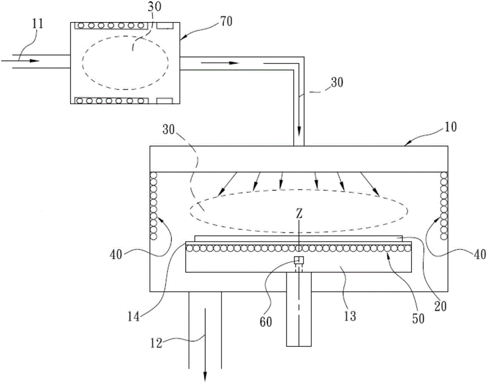
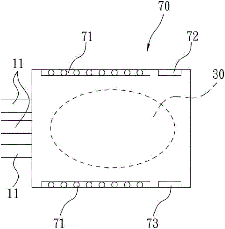
[0038] like figure 1 and figure 2 As shown, the present embodiment provides a preferred remote plasma-enhanced chemical vapor deposition device, which includes a reaction chamber 10 and a remote plasma generation chamber 70 communicated with each other, wherein one end of the remote plasma generation chamber 70 A process gas inlet 11 is provided, and a by-product outlet 12 is provided at the bottom of the reaction chamber 10 . A platform 13 is provided in the reaction chamber 10, and a heating device is provided in the platform 13, which can heat the substrate 20 to provide the temperature required for forming the plasma 30; a platform surface 14 is fixed on the platform 13 for bearing At least one substrate 20, the platform surface 14 here can preferably be set as a rotatable structure, so as to improve the film-forming effect of the reaction chamber. A DC discharge unit 71, a radio frequency discharge unit 72 and a microwave discharge unit 73 are simultaneously and mutual...

Embodiment 2

[0046] This embodiment proposes another preferred remote plasma-enhanced chemical vapor deposition device, which is basically the same as the device in Embodiment 1, with the difference that the setting parameters of each discharge unit and process gas are different.

[0047] In this embodiment, the radio frequency intensity of the radio frequency discharge unit 72 is preferably 11000MHz, 100A / m±3%, that is, when the frequency of the radio frequency discharge unit 72 is 11000MHz, the radio frequency can be in the range of (100±100*3%) A / m The DC intensity of the DC discharge unit 71 is 15KVA / m ± 10%, that is, the DC intensity can be selected within the range of (15 ± 15*10%) KVA / m; the radio frequency intensity of the microwave discharge unit 73 is 120db / w. In addition, the remote plasma generation chamber 70 also uses argon gas as the process gas, but the gas flow intensity of the argon gas is preferably 5˜15 cc / min. Compared with the first embodiment, the parameter range o...

Embodiment 3

[0049] This embodiment proposes a deposition method applicable to the remote plasma-enhanced chemical vapor deposition device, which specifically includes the following steps:

[0050] A: At least one substrate 20 is placed on the platform surface 14 in the reaction chamber 10 , here, the shape of the substrate 20 is not limited, and the number depends on the size of the platform surface 14 .

[0051] B: providing the plasma 30 formed by the process gas into the reaction chamber 10;

[0052] In this step, the plasma 30 is formed from raw materials in the remote plasma generation chamber 70 and then passed into the reaction chamber 10 .

[0053] C1: start the first electric field device 40, the first electric field device 40 is arranged on the peripheral wall of the inner cavity of the PECVD reaction chamber 10, and is used to generate an electric attraction effect on the plasma 30 in the reaction chamber 10, so that the plasma Before the source material or film precursor in 3...


PUM


Abstract

The invention discloses a far-end plasma reinforced chemical vapor deposition device and relates to the technical field of film preparation. The far-end plasma reinforced chemical vapor deposition device comprises a reaction chamber and a far-end plasma generation chamber communicating with the reaction chamber. A processing gas inlet is formed in the far-end plasma generation chamber. A byproduct exhaust port is formed in the reaction chamber. A platform is arranged in the reaction chamber. A substrate is placed on the platform surface of the platform. A direct-current discharging unit, a radio frequency discharging unit and a microwave discharging unit are simultaneously arranged in the far-end plasma generation chamber in an isolated mode. The direct-current discharging unit, the radio frequency discharging unit and the microwave discharging unit discharge synchronously so that the processing gas in the far-end plasma generation chamber can form plasma, and then the plasma is injected into the reaction chamber. Through the far-end plasma generation chamber, a plasma source meeting requirements is generated, the plasma density can be effectively controlled, the defect that the density of the formed plasma is low or space distribution is uneven is overcome, and the using efficiency and the processing efficiency of the far-end plasma reinforced chemical vapor deposition device are improved.

Description

technical field [0001] The invention relates to the technical field of film preparation, in particular to a remote plasma enhanced chemical vapor deposition device. Background technique [0002] Chemical Vapor Deposition (CVD, Chemical Vapor Deposition) is to introduce the source material (or reaction source, film precursor) into the reaction chamber in the form of gas (or process gas), through oxidation, reduction or reaction with the surface of the substrate A chemical reaction is carried out, and its products are deposited on the surface of the substrate by internal diffusion to form a thin film. [0003] Plasma has been widely used in various fields. For example, in the manufacture of semiconductor integrated circuits, the growth of thin films of different materials or the etching of circuits are generally realized by plasma technology. The reactants in the plasma are ions or free radicals with high chemical activity, and the surface of the substrate will also have high...

Claims


Application Information

Patent Timeline
Patent Type & Authority Applications(China)
IPC IPC(8): C23C16/517
CPCC23C16/517
Inventor 张宇顺
Owner 张宇顺
Why Eureka
Try Eureka