Disc drill bit with steerable wheel discs

A technology of roulette and drill bit, which is applied in the direction of drill bit, drilling equipment, earthwork drilling and mining, etc. It can solve the problems of short life of cutting teeth, aggravated wear of roulette ring gear, breakage of roulette ring gear, etc., so as to reduce wear and improve Rock-breaking efficiency and the effect of prolonging the service life

Active Publication Date: 2017-02-01
成都海纳能源科技有限公司
View PDF6 Cites 0 Cited by
  • Summary
  • Abstract
  • Description
  • Claims
  • Application Information

AI Technical Summary

Problems solved by technology

The lateral scraping of the rock by the roulette will directly cause the breakage and plastic deformation of the roulette ring, and aggravate the wear of the roulette ring
The main reason why disc drill bits are not really popularized and applied in the field is that the life of the cutting teeth is too short to meet the requirements of drilling

Method used


Image

  • Disc drill bit with steerable wheel discs
  • Disc drill bit with steerable wheel discs
  • Disc drill bit with steerable wheel discs

Examples


Embodiment 1

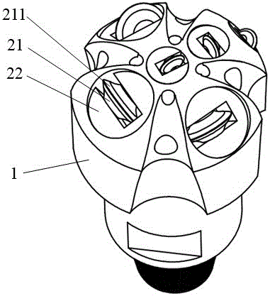
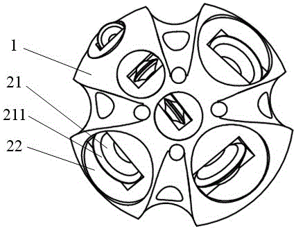
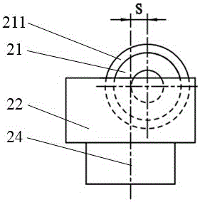
[0032] refer to Figure 1-6 As shown, a disc-type drill bit with a turnable roulette includes a drill body 1 and a roulette 21. The roulette 21 is provided with a ring gear 211. The roulette 21 can rotate relative to the drill body 1. The drill body 1 is provided with at least A steering wheel, the steering wheel is made up of a wheel 21 and a steering seat 22, the steering seat 22 is mounted on the drill body 1 through a rotational connection, the steering seat 22 can rotate relative to the drill body 1, and the wheel 21 is installed on the steering wheel through a rotational connection On the seat 22, the wheel disc 21 can rotate relative to the steering seat 22. Alternatively, as shown in this embodiment, the drill body 1 is correspondingly provided with a hole for accommodating a steering seat 22 matching the steering wheel, and the steering seat 22 enters the hole and rotates on the drill body 1 . Steering seat 22 can have various forms, for example image 3 , 5 Be tha...

Embodiment 2

[0034] This embodiment is basically the same as Embodiment 1, the difference being that: the wheel disc 21 and the steering seat 22 are connected by a shaft, and the shaft and the wheel disc 21 are connected by rotation. Or, the shaft and the wheel 21 are fixedly connected or the shaft and the wheel are integrated, and the shaft and the steering seat 22 are connected in rotation. Or, there is a rotational connection between the shaft and the wheel 21 , and a rotational connection between the shaft and the steering seat 22 .

Embodiment 3

[0036] This embodiment is basically the same as Embodiment 1, the difference being that a locking structure 4 is provided between the steering seat 22 and the drill body 1 to limit the movement of the steering wheel in the direction of the rotation axis 24 of the steering seat 22 . A circlip structure can be set between the steering seat 22 and the drill body 1 to prevent the steering wheel from moving in the direction of the rotation axis 24 of the steering seat 22 or falling off along the axis; Structure, the steering seat 22 is limited in the steering seat hole of the drill body 1 by the nut to prevent the steering wheel from moving or falling off in the direction of the rotation axis 24. As a further option, ball locking is adopted between the steering seat 22 and the drill bit body 1 (such as Figure 8 ).


PUM


Abstract

The invention discloses a disc drill bit with steerable wheel discs. The disc drill bit comprises a drill bit body and the wheel discs. Gear rings are arranged on the wheel discs. The wheel discs can rotate relative to the drill bit body. The disc drill bit is characterized in that at least one steerable wheel disc is arranged on the drill bit body, each steerable wheel disc is composed of a wheel disc body and a steering base, the steering bases are installed on the drill bit body in a rotatable connection mode and can rotate relative to the drill bit body, the wheel disc bodies can be installed on the steering bases in a rotatable connection mode and can rotate relative to the steering bases, the rotating axis of each wheel disc body is offset relative to the rotating axis of the corresponding steering base, the offset distance is larger than one twentieth of the radius of each wheel disc gear ring and smaller than three times of the diameter of each wheel disc gear ring, and the rotating axis of each steerable wheel disc close to the core of the drill bit does not coincide with the axis of the drill bit. According to the disc drill bit, the rock breaking efficiency of the drill bit can be improved while the problem that cutting teeth of a disc drill bit are short in service life is solved.

Description

technical field [0001] The invention belongs to the technical field of drilling equipment such as petroleum and natural gas, mining engineering, building foundation engineering construction, geology, hydrology, etc., and particularly relates to a disc drill bit. Background technique [0002] The drill bit is a rock-breaking tool used in drilling engineering to break rock and form a wellbore. Disc drill bit (also known as disc drill bit, disc drill bit or disc drill bit) is a roller cone bit with a new tooth structure. Angled annular continuous or intermittent ring gear. The rock breaking mechanism of the disc drill bit is different from that of the conventional roller cone bit. When the ring gear rolls along the rock, it uses a large contact stress to force the rock to break, forming an annular rock breaking zone. Because the ring gear is circular, it is convenient for the continuous rolling of the cone (or disc) on the rock. Therefore, compared with the tri-cone bit, the ...

Claims


Application Information

Patent Timeline
Patent Type & Authority Applications(China)
IPC IPC(8): E21B10/12E21B10/16E21B10/50E21B10/25
CPCE21B10/12E21B10/16E21B10/25E21B10/50
Inventor 陈炼杨迎新黄丹兰谢宗亮
Owner 成都海纳能源科技有限公司
Why Eureka
Try Eureka