
Biomass boiler for boiler front flue gas drying and continuous bale combustion

A biomass boiler and drying technology, applied in the direction of climate sustainability, combustion methods, combustion equipment, etc., to reduce grate corrosion, reduce moisture, and prevent coking

Active Publication Date: 2017-02-01
HAILUN LIMIN ENERGY SAVING BOILER MFG
View PDF2 Cites 10 Cited by
  • Summary
  • Abstract
  • Description
  • Claims
  • Application Information

AI Technical Summary

Problems solved by technology

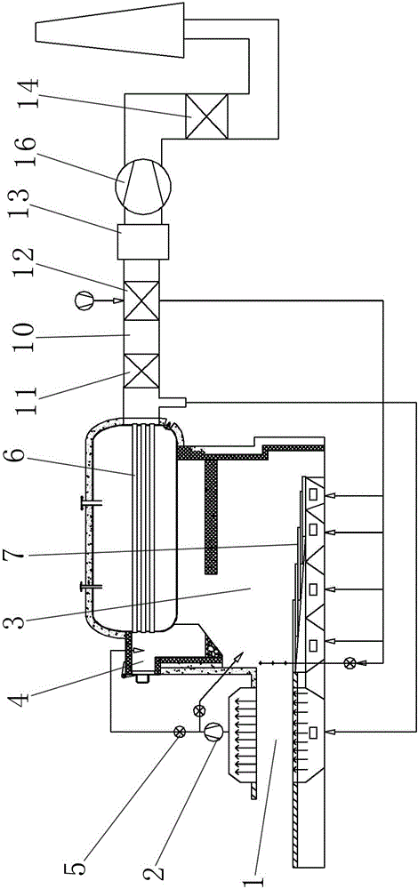
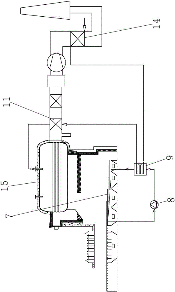
[0005] A biomass boiler with flue gas drying in front of the furnace, which is continuously bundled and fired. The smoke inlet device draws hot flue gas at 350-400°C to dry the bundled biomass. A smoke exhaust device and an induced draft fan 1 are installed above the drying area to suck the hot flue gas sent from the bottom and dry the grass The moisture in the bundle is sucked out, and at the same time, under the suction of the induced draft fan 1, a small part of the high-temperature flue gas in the furnace is also sucked into the bundle, which is dried like smoking and ignites the biomass. The smoke exhaust device is connected to the air inlet of the induced draft fan 1 , the air outlet of the induced draft fan 1 is respectively connected with the furnace and the front smoke box of the biomass boiler body, and a flow regulating valve is respectively set between the air outlet of the induced draft fan 1 and the furnace and the front smoke box of the biomass boiler body. The flue gas flow in the furnace and the front smoke box is controlled, and the water vapor-containing flue gas entering the furnace plays a role in controlling the furnace temperature, which is conducive to reducing the generation of NOx; The temperature of the flue gas is lowered to solve the problem of clogging the entrance of the threaded smoke pipe and the accumulation of dust in the pipe;

Method used


Image

  • Biomass boiler for boiler front flue gas drying and continuous bale combustion
  • Biomass boiler for boiler front flue gas drying and continuous bale combustion

Examples


Embodiment Construction

[0014] refer to figure 1 and figure 2 , a biomass boiler with flue gas drying in front of the furnace and continuous bundled firing, which includes a biomass boiler body, a drying area 1 is arranged before the feed port of the biomass boiler body, and a smoke inlet device is arranged at the bottom of the drying area 1, The hot flue gas at 350-400°C is sucked in from the smoke inlet device in the drying area 1, and the bundled biomass is dried. A smoke exhaust device and an induced draft fan 1 are installed above the drying area 1, and the smoke sent from the bottom is sucked. The hot flue gas sucks out the moisture in the bale, and at the same time, under the suction of the induced draft fan 1, a small part of the high-temperature flue gas in the furnace 3 is also sucked into the bale, drying and igniting the biomass like smoking. The smoke exhaust device and The air inlet of induced draft fan one 2 is connected, and the gas outlet of induced draft fan one 2 is respectively ...


PUM


Abstract

The invention discloses a biomass boiler for boiler front flue gas drying and continuous bale combustion, and belongs to the technical field of biomass combustion. By adoption of the biomass boiler, problems of an existing biomass bale combustion technology are solved. The biomass boiler comprises a biomass boiler body. A drying area is arranged in front of a feed inlet of the biomass boiler body. Baled biomass is fed into the feed inlet after passing through the drying area. A water-cooling reciprocating grate is arranged at the bottom of a hearth of the biomass boiler body. A flue gas suction port is formed in a tail flue of the biomass boiler body and connected with a flue gas inlet device arranged at the bottom of the drying area. A coal economizer, an air pre-heater, a bag type dust collector, a second induced draught fan and a condensing heat exchanger are sequentially distributed in the tail flue of the biomass boiler body, wherein the air pre-heater is connected with and provides pre-heated air for an air chamber at the bottom of the hearth and secondary air ports formed in the two sides of a front arch of the hearth; and the condensing heat exchanger is sequentially connected with the water-cooling reciprocating grate, the coal economizer and a steam pocket of the biomass boiler body. The biomass boiler for boiler front flue gas drying and continuous bale combustion is used for combustion of baled biomass.

Description

technical field [0001] The invention belongs to the technical field of biomass combustion, and in particular relates to a furnace flue gas drying continuous bundled combustion biomass boiler. Background technique [0002] With the intensification of the greenhouse gas effect caused by the consumption of fossil energy, it is imminent to find a clean and reliable energy source. Biomass energy is widely regarded as a "CO 2 Therefore, the application of biomass energy has received extensive attention worldwide, and biomass combustion technology is currently the most mature biomass application technology. [0003] Due to the scattered sources of crop straw, certain costs are required for collection, transportation, and storage. At present, it is mainly sent to a biomass power plant in bundles (packages), and then burned to generate electricity after being broken up, or processed into briquettes after drying. Since the briquette fuel is 800-1000 yuan per ton, the economy is poor,...

Claims


Application Information

Patent Timeline
IPC IPC(8): F23B30/10F23B80/00F23J15/06F23K1/04
CPCF23B30/10F23B80/00F23J15/06F23K1/04F23K2201/20Y02E20/30
Inventor 别如山顾文波万显君
Owner HAILUN LIMIN ENERGY SAVING BOILER MFG
Learn More