Main grid-free full-back contact solar cell module

A solar cell, full-back contact technology, applied in the field of solar cells, can solve the problems of incompatibility, rising cost, and difficulty in collecting holes, and achieve the effects of improving filling factor, reducing resistance loss, and reducing consumption.

Active Publication Date: 2017-02-15
晶澳(扬州)新能源有限公司
View PDF6 Cites 19 Cited by
  • Summary
  • Abstract
  • Description
  • Claims
  • Application Information

AI Technical Summary

Problems solved by technology

In the previous production process of full back contact solar cells, the metallization process is mostly realized by electroplating with a relatively complicated process. This method does have excellent performance in reducing the series resistance of back contact cells and increasing the open circuit voltage of cells. The process is complicated, the waste discharged seriously pollutes the environment, and is not compatible with the mainstream metallization method of industrial production, so it is difficult to promote low-cost industrialization
[0005] The metallization of the back contact battery using the current mainstream screen printing technology, if the conventional busbar design is used, the two main problems are (1): between the main grid line and the opposite electrode fine grid line and the busbar line Insulation between doped regions corresponding to opposite electrodes
(2) Because the current of the full back contact battery is significantly higher than that of the conventional battery, in order to reduce the power loss caused by the line resistance on the main grid line and the thin grid line, a wider grid line is required, and more slurry consumption brings cost a sharp rise in
However, the disadvantage of this method is that due to the lateral transmission distance, the electrons corresponding to the position of the main grid of the positive electrode are difficult to be collected by the negative electrode, and the holes corresponding to the position of the main grid of the negative electrode are difficult to be collected by the positive electrode.
In this way, the fill factor and photoelectric conversion efficiency of the battery are greatly affected

Method used


Image

  • Main grid-free full-back contact solar cell module
  • Main grid-free full-back contact solar cell module
  • Main grid-free full-back contact solar cell module

Examples


Embodiment 1

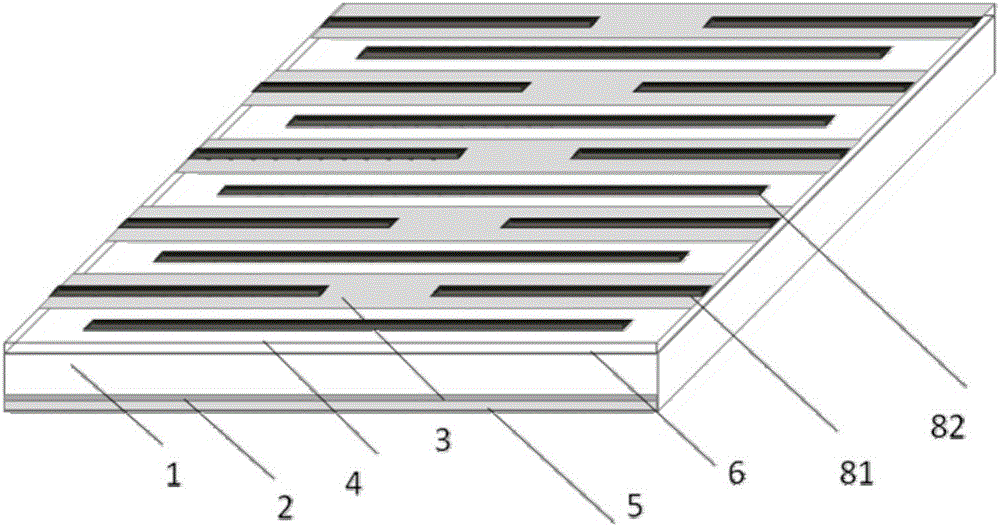
[0040] Such as Figure 1-5 As shown, the busbar-less full back contact solar cell assembly provided in this embodiment includes a plurality of back contact small solar cells connected in series, the back contact solar small cells are cut from the back contact solar cells, and the back contact solar cells The small battery sheet includes an n-type silicon substrate 1, on the back of the n-type silicon substrate 1 there are p+ doped regions 3 and n+ doped regions 4 arranged in parallel and alternately, on the p+ doped regions 3 and n+ doped regions 4 A passivation layer 6 is provided, and a positive electrode fine grid 81 is arranged on the passivation layer 6. The positive electrode fine grid 81 is located at the corresponding position of the p+ doped region 3 and is in contact with the p+ doped region 3. A negative electrode fine grid 82 is provided, and the negative electrode fine grid 82 is located at the corresponding position of the n+ doped region 4 and is in contact with...

Embodiment 2

[0063] The difference with embodiment 1 is:

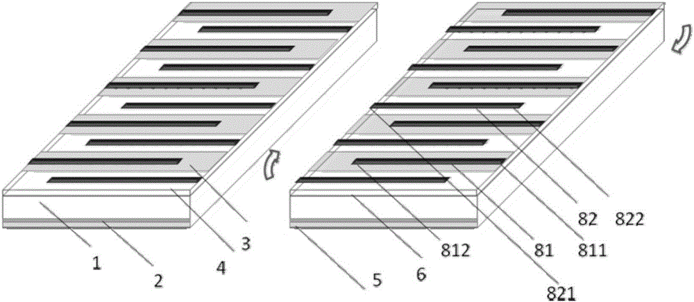
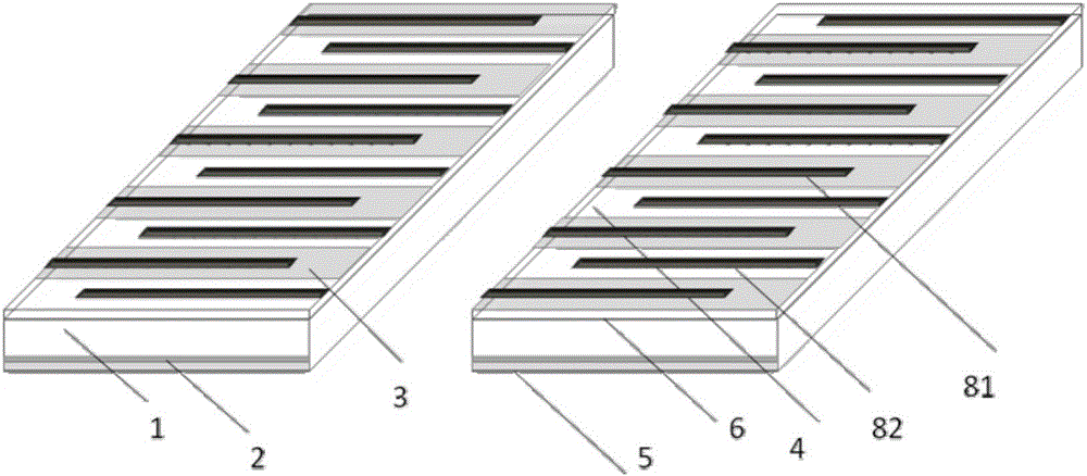
[0064] Such as Figure 6-7 As shown, the protruding end of the negative electrode fine grid of one of the back-contacted small solar cells is connected in series with the protruding end of the positive electrode fine grid of an adjacent back-contacted solar small cell, and the positive electrode fine grid and the The current of the negative electrode fine grid is conducted in the direction of the positive electrode fine grid and the negative electrode fine grid.

[0065] An n+ doped region is provided at the corresponding position where the solder strip is in contact with the silicon substrate on the shortened end side of the positive electrode fine grid of one of the back-contacted small solar cells, and the solder strip is connected to the negative side of the adjacent small solar cell. A p+ doped region is provided at the corresponding position where the silicon substrate on the side of the shortened end of the fine grid of the...


PUM


Abstract

The invention discloses a main grid-free full-back contact solar cell module. The solar cell module comprises a plurality of series back contact small solar cell sheets, the back contact small solar cell sheet is formed after cutting the back contact solar cell sheet, a protruding end of a fine grid of one back contact small solar cell sheet is serially connected with the protruding end of the fine grid with opposite polarity of the adjacent back contact small solar sheet to manufacture a series cell string and then to manufacture the cell module; the cell module avoids the efficiency loss and process complexity caused by the main grid line setting of the full-back contact solar cell and saves the main grid line cost; since a plurality of cell units are cut, the current of each string of cell sheet group string is lowered, thereby reducing the influence of the fine grid line resistance loss; the consumption of the silver paste can be lowered, and the fill factor of the battery and the module are improved at the same time; based on two above points, the cell module can improve the efficiency of the full-back contact battery module, and can lower the process difficulty and manufacturing cost thereof.

Description

technical field [0001] The invention belongs to the field of solar cells, and in particular relates to a full back contact solar cell assembly without main grid. Background technique [0002] A solar cell is a semiconductor device that converts light energy into electrical energy. Lower production costs and higher energy conversion efficiency have always been the goals pursued by the solar cell industry. For conventional solar cells at present, the positive electrode contact electrode and the negative electrode contact electrode are respectively located on the front and back sides of the battery sheet. The front of the battery is the light-receiving surface, and the coverage of the metal positive electrode on the front will inevitably cause a part of the incident sunlight to be reflected by the metal electrode, resulting in a part of optical loss. The coverage area of ​​the front metal electrode of an ordinary crystalline silicon solar cell is about 7%, and reducing the fro...

Claims


Application Information

Patent Timeline
Patent Type & Authority Applications(China)
IPC IPC(8): H01L31/0224H01L31/05
CPCY02E10/50H01L31/022441H01L31/0516
Inventor 蒋秀林陈孝业段光亮尹海鹏单伟
Owner 晶澳(扬州)新能源有限公司
Why Eureka
Try Eureka