
A control system of a hand-held polishing machine with stable pressure

A control system and stable pressure technology, applied in the field of mechanical parts, can solve the problems of unstable polishing quality and high technical requirements, and achieve the effects of easy human control, low technical requirements and simple operation

Active Publication Date: 2018-08-31
重庆前进焊接材料制造有限公司
View PDF7 Cites 0 Cited by
  • Summary
  • Abstract
  • Description
  • Claims
  • Application Information

AI Technical Summary

Problems solved by technology

[0003] In the process of using a hand-held polishing machine, most of the polishing pressure is applied manually, which requires high technical requirements for the staff, and the polishing quality is unstable

Method used


Image

  • A control system of a hand-held polishing machine with stable pressure

Examples


Embodiment 1

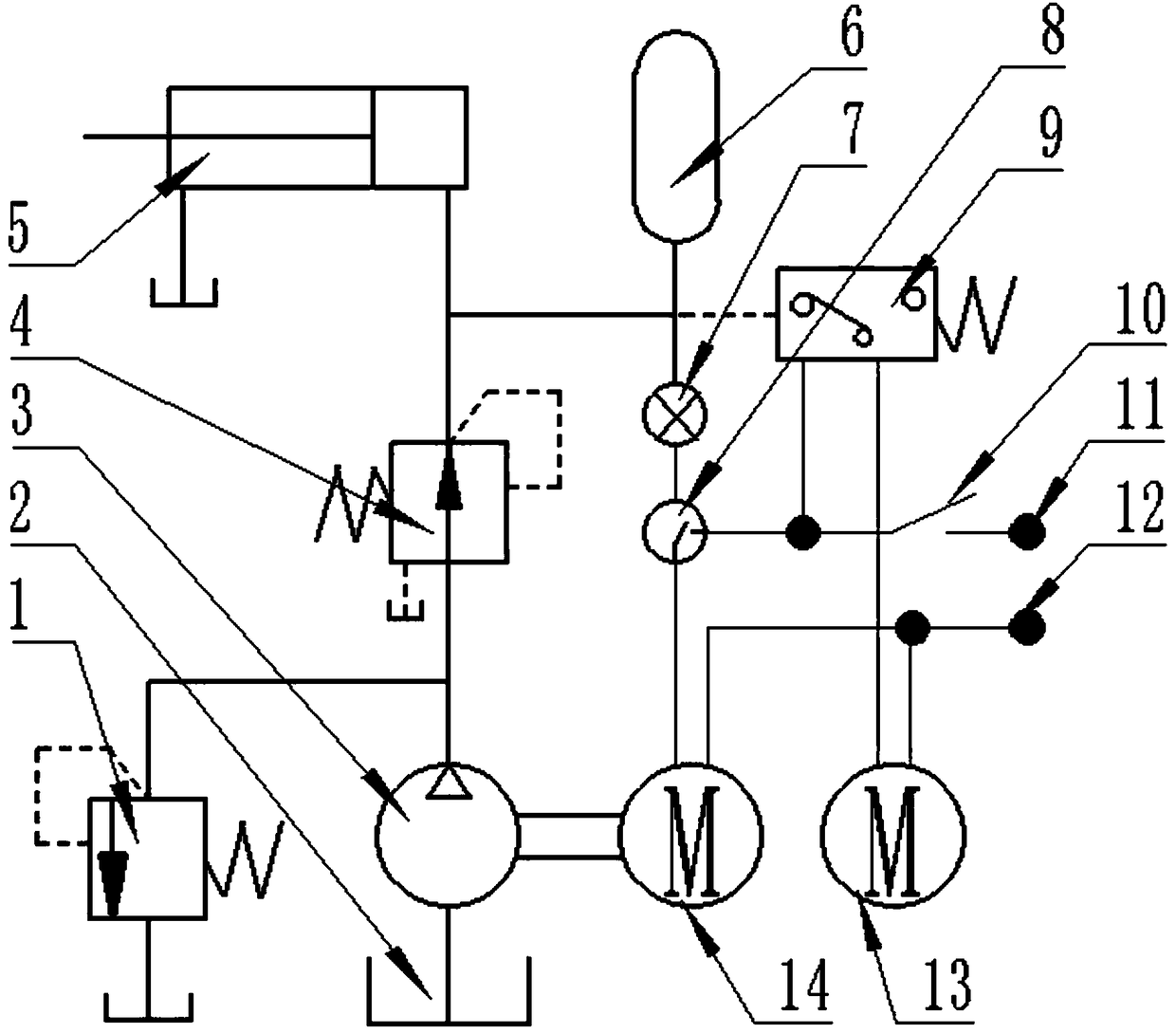
[0021] Such as figure 1 As shown, in order to overcome the defects of the prior art, the present invention provides a control system for a pressure-stabilized handheld polishing machine, which includes an oil tank 2, a hydraulic oil pump 3, a pressure reducing valve 4, a hydraulic cylinder 5, a pressure measuring device 7, CPU 8, pressure switch 9, manual switch 10, power supply positive pole 11, power supply negative pole 12, first motor 13 and second motor 14; the oil tank 2 is connected to the liquid inlet end of the hydraulic oil pump 3, and the liquid outlet of the hydraulic oil pump The end is connected to the liquid inlet end of the pressure reducing valve 4, the liquid outlet end of the pressure reducing valve 4 is respectively connected to the rodless cylinder of the hydraulic cylinder 5, the pressure measuring device 7 and the control end of the pressure switch 9, and the rod cylinder of the hydraulic cylinder 5 is connected to the oil tank 2. The positive pole 11 of...

Embodiment 2

[0025] This embodiment is further improved on the basis of embodiment 1, as figure 1 As shown, a safety valve 1 is arranged between the hydraulic oil pump 3 and the pressure reducing valve 4. Prevent the safety accident caused by the jamming of the pressure reducing valve 4 to generate pressure.

[0026] In order to make the system pressure more stable, an accumulator 6 is arranged between the pressure reducing valve 4 and the hydraulic cylinder 5 .

[0027] In order to enable the central processing unit 8 to control the opening and closing of the circuit, a normally closed switch is provided in the central processing unit 8, the opening pressure of the normally closed switch is greater than the closing pressure of the normally closed switch, and the disconnection of the normally closed switch The pressure is equal to the rated output pressure of the pressure reducing valve 4.

[0028] In order to make the system work stably and reliably, the pressure switch 9 is a normally ...


PUM


Abstract

The invention discloses a stable pressure control system for a handheld polisher, comprising an oil tank, a hydraulic oil pump, a relief valve, a hydraulic cylinder, a pressure measurer, a central processing unit, a pressure switch, a manual switch, a power positive pole, a power negative pole, a first motor and a second motor; the oil tank is connected with the hydraulic oil pump which is connected with the relief valve, the relief valve is connected respectively with the hydraulic cylinder, the pressure measurer and thee pressure switch, and the hydraulic cylinder is connected to the oil tank; the power positive pole is connected to the manual switch, the manual switch is connected respectively to the pressure switch and the central processing unit, the pressure switch is connected to the first motor, the first motor is connected to the power negative pole, the central processing unit is connected to the pressure measurer, the central processing unit is connected to the second motor, the second motor is connected to the power negative pole, and the power output end of the second motor is connected to the hydraulic oil pump. The stable pressure control system provides automatic pressure control and has stable pressure, can provide reliable polishing quality for a polisher and has low technical skill requirements on workers.

Description

technical field [0001] The invention relates to the technical field of mechanical parts, in particular to a control system for a hand-held polishing machine with stable pressure. Background technique [0002] Polishing machines, also known as grinders, are often used for mechanical grinding, polishing and waxing. Its working principle is: the motor drives the sponge or wool polishing disc installed on the polishing machine to rotate at high speed. Due to the joint action of the polishing disc and the polishing agent and friction with the surface to be polished, it can achieve the effect of removing paint surface pollution, oxide layer and shallow marks. Purpose. The speed of the polishing disc is generally 1500-3000r / min, mostly stepless speed change, which can be adjusted at any time during construction. [0003] In the process of using a hand-held polishing machine, most of the polishing pressure is manually applied, which requires high technical requirements for the sta...

Claims


Application Information

Patent Timeline
Patent Type & Authority Patents(China)
IPC IPC(8): B24B51/00B24B29/00
CPCB24B29/00B24B51/00
Inventor 温晓琳
Owner 重庆前进焊接材料制造有限公司
Learn More