Cyclic heating high efficiency 3D printer nozzle device

A 3D printer, cycle heating technology, applied in coating devices, processing heating elements, 3D object support structures, etc., can solve the problems of easy blockage of nozzles, low efficiency of nozzle filament output, and melting of nozzle filaments, etc., to prevent Premature softening of consumables, poor heat dissipation effect, and avoiding the accumulation of waste heat

Inactive Publication Date: 2017-02-22
HUNAN RUIDU TECH
View PDF4 Cites 15 Cited by
  • Summary
  • Abstract
  • Description
  • Claims
  • Application Information

AI Technical Summary

Problems solved by technology

[0003] Among them, the raw materials need to be melted by a heating block before use. Generally, an independent heating component is installed in the heating block, and the heating block is heated by the heating component to melt the silk material. However, the temperature distribution in the existing heating block is uneven, resulting in the nozzle The silk material inside is not evenly melted, and it appears lumpy, which may block the nozzle or print the model poorly; and in the heating process, it is also necessary to have a heat dissipation pipe to dissipate the heat, but the existing technology only directly dissipates heat through the heat dissipation pipe , due to the limited heat dissipation area, the heat dissipation effect is not good, the temperature in the heat dissipation end is in a high state, and the raw material and consumables are softened prematurely in the heat dissipation end, resulting in low filament output efficiency of the nozzle, easy blockage of the nozzle, and difficulty in extrusion of consumables. There will be a lot of noise during work, and the current heat dissipation is generally realized by man, with a low degree of automation; and the existing heating components can only be heated once, and the effect is average

Method used


Image

  • Cyclic heating high efficiency 3D printer nozzle device
  • Cyclic heating high efficiency 3D printer nozzle device

Examples


Embodiment Construction

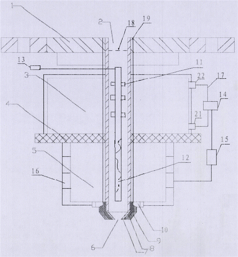
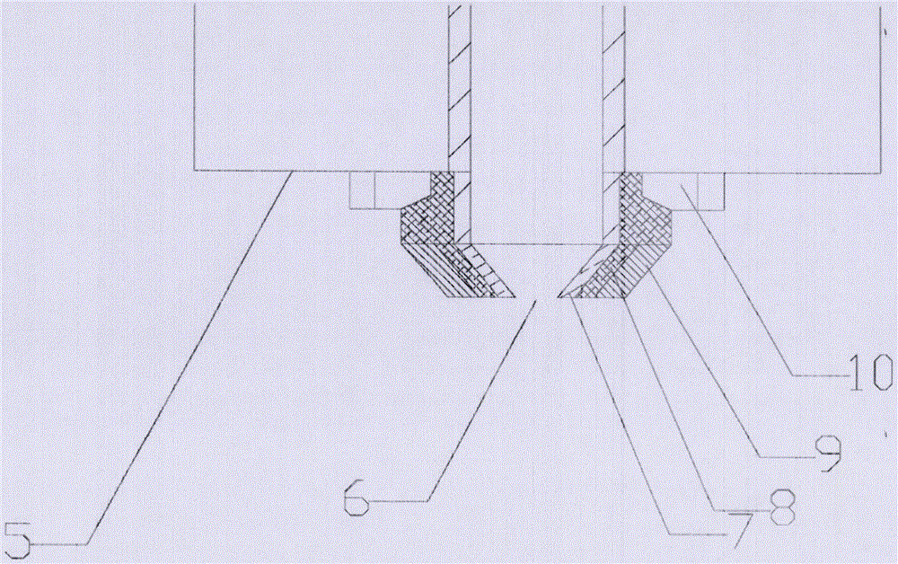
[0020] The following will combine figure 1 , figure 2 The present invention is described in detail, and the exemplary embodiments and descriptions of the present invention are used to explain the present invention, but not to limit the present invention.

[0021] A high-efficiency 3D printer nozzle device capable of circulating heating, including a substrate 1, a feeding pipe 2 is arranged in the middle of the substrate 1, the main body of the feeding pipe 2 is located below the substrate 1, and the bottom of the feeding pipe 2 is a nozzle 6. In the feeding pipe The outer side of the upper part of 2 is provided with a heat dissipation part 3, which is used to ensure that the temperature of the material is the same as that of the outside world, so that the material in the feeding pipe can move normally in it, and the outside of the lower part of the feeding pipe 2 is a heating part 5, and the effect of the heating part 5 is to make the The temperature of the material increase...


PUM

PropertyMeasurementUnit
thicknessaaaaaaaaaa

Abstract

The invention relates to a cyclic heating high efficiency 3D printer nozzle device, including a base plate, the middle of the base plate is provided with a feeding tube, the main body of the feeding tube is located below the base plate, the lowermost of the feeding tube is a nozzle, the upper outer side of the feeding tube is provided with a heat dissemination component, the outside of the lower part of the feeding tube is a heating component, the outer wall of the nozzle is constructed from multiple layered structures, the inner layer is a main heat conducting layer, which is touched and fixed with an elastic thermal preservation layer outside the main heat conducting layer, the outer side of the elastic thermal insulation layer is an outer wall, the top of the elastic thermal preservation layer is provided with a compression rod, the inside of the feeding tube is provided with a rotating shaft, the rotation of which is driven by a motor, the heat dissemination component includes a heat dissemination tube and a liquid heat dissemination device connected with the heat dissemination tube, the liquid heat dissemination device is connected with a control device, the control device through controlling a temperature sensor provided on the heat dissemination tube performs a heat disseminating control to the materials in the feeding tube. The device has good performance on heating and disseminating heat, and has obvious effect on anti clogging.

Description

technical field [0001] The invention relates to the technical field of 3D printers, in particular to a high-efficiency 3D printer nozzle device capable of circulating heating. Background technique [0002] 3D printing technology is an advanced manufacturing technology that uses point-by-point or layer-by-layer molding methods to manufacture physical models, molds and parts. It is a new manufacturing technology that integrates advanced technologies such as material science, CAD\CAM, numerical control and laser. The technology is based on the idea of ​​discrete and stacked molding. The 3D CAD model of the part built on the computer is sliced ​​in layers along the height direction to obtain the section information of each layer, and then output to the rapid prototyping equipment to scan and fill layer by layer, and then glue along the height direction. Combined and superimposed, three-dimensional solid parts are gradually formed. Compared with the traditional machining process of...

Claims


Application Information

Patent Timeline
Patent Type & Authority Applications(China)
IPC IPC(8): B29C64/118B29C64/20B29C64/209B29C64/295B33Y30/00
CPCB33Y30/00
Inventor 彭新桥
Owner HUNAN RUIDU TECH
Why Eureka
Try Eureka