Internal combustion engine tail gas utilization heat energy power system based on honeycomb cavity gasification

A power system and internal combustion engine technology, applied in the field of energy utilization equipment, can solve the problems of small external waste heat absorption rate, small amount of work, unstable gasification temperature of working fluid, etc., to improve gasification efficiency and condensation efficiency, and stabilize gasification Temperature and working medium flow rate, avoiding the effect of turbine speed instability

Inactive Publication Date: 2017-02-22
郭远军
View PDF0 Cites 0 Cited by
  • Summary
  • Abstract
  • Description
  • Claims
  • Application Information

AI Technical Summary

Problems solved by technology

[0007] However, the common problems of existing thermal power generation equipment are: a. The temperature requirements for high-temperature heat sources are high, generally above 200°C, and the thermal energy conversion efficiency is low. The thermal energy conversion efficiency is generally 15% to 35%. Under the heat source of ℃, the average thermal energy conversion efficiency is 18%; b. The gasification of the working fluid in the gasification device is prone to incomplete gasification, the volume expansion is small, and the amount of external work in a single cycle of the gasification process is small; c. The gasification temperature is unstable, the condensation effect of the working medium is not good, and the working medium is easy to deteriorate or appear impurities; d. The driving force of the turbine is small, and the efficiency of converting the external work of the gasification medium into mechanical energy is low; e. The speed of the turbine is unstable, and It is prone to stuck problems; f. The heat collection effect of the heat collection device is not good, and the external waste heat absorption rate is small; g. The heat displacement of the condensing device is large, and the heat energy is wasted. The condensation speed through natural condensation is slow, and the use of Active condensation mode (fan air cooling or liquid pump water cooling) requires additional power consumption
[0008] On the other hand, the thermal energy conversion efficiency of the existing internal combustion engine is about 45%, and the exhaust temperature of the internal combustion engine exhaust gas can be as high as 400°C, and there is a large energy waste in the exhaust emission.

Method used


Image

  • Internal combustion engine tail gas utilization heat energy power system based on honeycomb cavity gasification
  • Internal combustion engine tail gas utilization heat energy power system based on honeycomb cavity gasification
  • Internal combustion engine tail gas utilization heat energy power system based on honeycomb cavity gasification

Examples


Embodiment 1

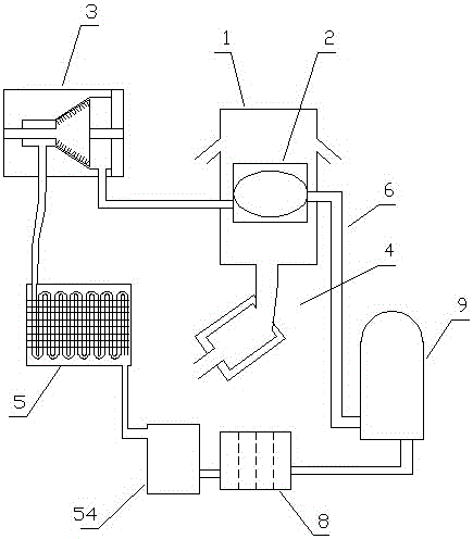
[0082] Example 1 (such as figure 1 shown): a thermal energy power system based on honeycomb cavity gasification of exhaust gas from an internal combustion engine, including a heat collector 1, a gasification device 2, a turbine 3, an internal combustion engine exhaust pipe 4, a condensing device 5, a circulation pipeline 6, and a circulating working medium 7 And the one-way hydraulic pump 9, the gasification device 2, the turbine 3, the condensing device 5 and the one-way hydraulic pump 9 are in turn communicated through the circulation pipeline 6, and the circulation pipeline 6 contains the circulating working medium 7, and the heat collector 1 is installed in the gas. outside the chemical device 2;

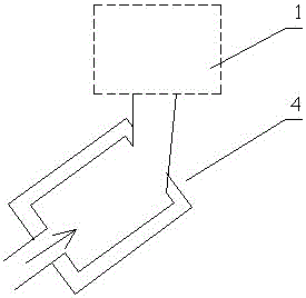
[0083] (like figure 2 shown) the exhaust pipe 4 of the internal combustion engine communicates with the heat collecting device 1;

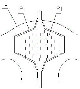
[0084] (like image 3 , Figure 4 shown) the gasification device 2 includes a gasification chamber 21, and the gasification chamber 21 is a ca...

Embodiment 2

[0094] Example 2 (such as Figure 9 shown): The difference from the first embodiment is that: the lower part of the upper cover 11 of the heat collecting device 1 is distributed with two layers of upper cover protrusion rings 111, and the upper part of the lower cover 12 of the heat collecting device 1 is distributed with two layers of lower cover protrusions Ring 121, the upper cover protrusion ring 111 and the lower cover protrusion ring 121 are staggered.

[0095] Through experiments on the thermal energy power system of the exhaust gas of the internal combustion engine based on the gasification of the honeycomb cavity in the above-mentioned embodiment 2, exhaust gas of different temperatures is discharged into the heat collecting device 1, and the exhaust gas displacement is 1.5L / s. The exhaust gas of an internal combustion engine based on honeycomb cavity gasification is adjusted by the operation stability of the thermal power system; the experimental results are: when th...

Embodiment 3

[0096] Example three (such as Figure 10 shown): the difference from the first embodiment is: the lower part of the upper cover 11 of the heat collecting device 1 is distributed with three layers of upper cover protruding rings 111, and the upper part of the lower cover 12 of the heat collecting device 1 is distributed with three layers of lower cover protruding rings 121 , the upper cover protrusion ring 111 and the lower cover protrusion ring 121 are staggered.

[0097] By conducting experiments on the thermal energy power system of the exhaust gas of the internal combustion engine based on the gasification of the honeycomb cavity in the above-mentioned embodiment 3, exhaust gas of different temperatures is discharged into the heat collecting device 1, the exhaust gas displacement is 1.5L / s, and the flow rate of the working medium in the circulation pipe is based on The exhaust gas of an internal combustion engine based on honeycomb cavity gasification is adjusted by the ope...


PUM

PropertyMeasurementUnit
boiling pointaaaaaaaaaa

Abstract

The invention discloses an internal combustion engine tail gas utilization heat energy power system based on honeycomb cavity gasification. The system comprises a gasifying device, a turbine, a condensing device and a one-way hydraulic pump, wherein the gasifying device, the turbine, the condensing device and the one-way hydraulic pump communicate in a circulating mode in sequence through circulating pipes; the circulating pipes are filled with circulating working mediums; a heat collecting device is mounted at the external of the gasifying device, and is communicated with an internal combustion engine tail gas pipe; the gasifying device includes a gasification cavity; the gasification cavity is a cavity for realizing gasification of a working medium in the gasifying device; the gasifying device is positioned in a heat collecting cavity; and the gasification cavity takes the shape of a honeycomb cavity. The internal combustion engine tail gas utilization heat energy power system based on honeycomb cavity gasification has such advantages as high gasification efficiency, high heat energy conversion efficiency and power adjustability.

Description

technical field [0001] The invention belongs to the field of energy utilization equipment, in particular to a thermal energy power system for utilizing the exhaust gas of an internal combustion engine based on honeycomb cavity gasification. Background technique [0002] Energy is an important material basis for the survival and development of human society. Throughout the history of the development of human society, every major progress of human civilization is accompanied by the improvement and replacement of energy. The development and utilization of energy has greatly promoted the development of the world economy and human society. [0003] However, with the continuous development and consumption of energy, non-renewable energy sources such as oil, coal mines, and natural gas are gradually reduced, and energy conservation and recycling are gradually being paid attention to. The basic content of my country's current energy strategy is: adhere to the priority of saving, b...

Claims


Application Information

Patent Timeline
Patent Type & Authority Applications(China)
IPC IPC(8): F01N5/02F01K23/10F01K25/10F28B7/00B01D35/02
CPCB01D35/02F01K23/10F01K25/10F01K25/106F01N5/02F28B7/00Y02T10/12
Inventor 郭远军
Owner 郭远军
Why Eureka
Try Eureka