
A high-efficiency and low-nox segmental coupled combustion method for inferior coal

A combustion method and low-quality coal technology, applied in the direction of combustion method, graded combustion, combustion type, etc., can solve the problems of low NOx emission and high combustion efficiency at the same time, and achieve the effect of non-slagging load response and low NOx combustion

Active Publication Date: 2018-09-07
HARBIN INST OF TECH
View PDF6 Cites 0 Cited by
  • Summary
  • Abstract
  • Description
  • Claims
  • Application Information

AI Technical Summary

Problems solved by technology

[0008] The present invention aims to solve the problem that the existing coal combustion technology cannot realize low NOx emission and high combustion efficiency at the same time when low-quality coal is used as fuel, and the problem that a coal grinding system needs to be equipped in the combustion process provides a segmented coupling of low-quality coal with high efficiency and low NOx burning method

Method used


Image

  • A high-efficiency and low-nox segmental coupled combustion method for inferior coal
  • A high-efficiency and low-nox segmental coupled combustion method for inferior coal
  • A high-efficiency and low-nox segmental coupled combustion method for inferior coal

Examples


specific Embodiment approach 1

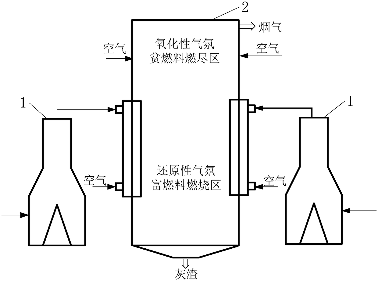
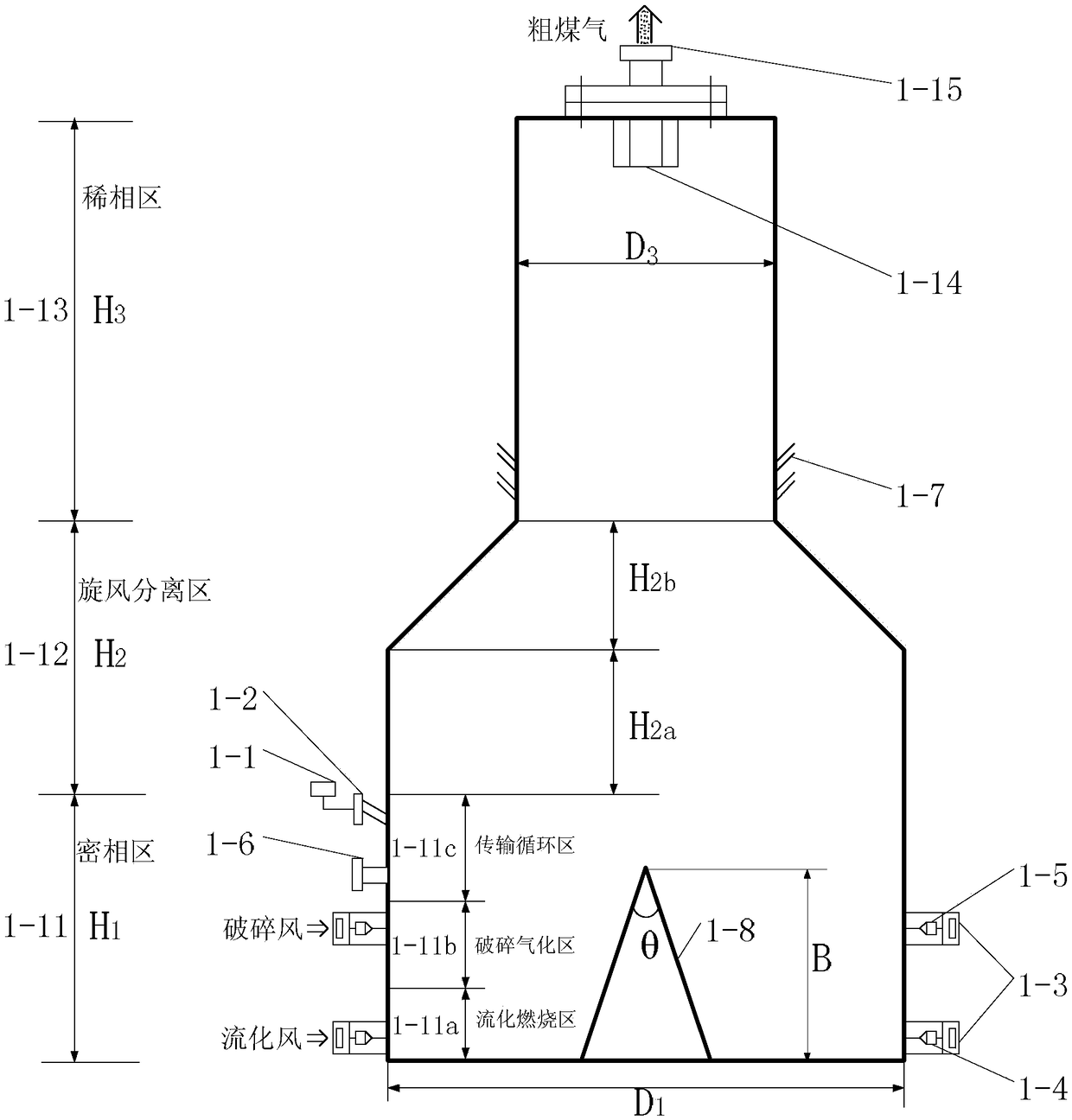
[0047] Specific implementation mode one: see figure 1 , figure 2 and Figure 4 Describe this embodiment, a high-efficiency and low-NOx segmented coupling combustion method for inferior coal described in this embodiment is realized by a high-efficiency and low-NOx segmental coupling combustion device for inferior coal, and the high-efficiency and low-NOx segmental coupling of the inferior coal The combustion device includes N fluidized beds 1 and a pulverized coal furnace 2, and the raw gas output pipes 1-15 of the N fluidized beds 1 are all communicated with the crude gas burner 2-4 of the pulverized coal furnace 2, and N is greater than or an integer equal to 1,

[0048] The fluidized bed 1 includes three reaction zones, which are dense phase zone 1-11, cyclone separation zone 1-12 and dilute phase zone 1-13 from bottom to top,

[0049] A central cone 1-8 is provided at the bottom of the fluidized bed 1, and a louver 1-14 is provided at the top, and both the central cone ...

specific Embodiment approach 2

[0070] Specific implementation mode two: see figure 1 , figure 2 and Figure 4 To illustrate this embodiment, the difference between this embodiment and the high-efficiency, low-NOx staged coupling combustion method for low-quality coal described in Embodiment 1 is that the area where the crude gas burner 2-4 is located is a reducing atmosphere rich The fuel combustion zone 2-2, the area above where the crude gas burner 2-4 is located is the oxidizing atmosphere lean fuel burnout zone 2-3.

[0071] In this embodiment, the crude gas nozzle 2-5a of the pulverized coal furnace 2 communicates with the crude gas output pipe 1-15 of the fluidized bed 1, and multiple groups of crude gas burners 2-4 need to be configured. Gas burners 2-4 are configured in 4 groups.

[0072]4 groups of crude gas burners 2-4 are arranged in a reducing atmosphere fuel-rich combustion area 2-2 in a tangential manner, and are used for the combustion of crude gas 1100°C in a reducing atmosphere rich in ...

specific Embodiment approach 3

[0075] Specific implementation mode three: see figure 1 , figure 2 and Figure 4 This embodiment is described. The difference between this embodiment and the high-efficiency, low-NOx staged coupled combustion method for low-quality coal described in Embodiment 1 is that:

[0076] In step 1, the air distribution method of injecting the fluidizing air nozzles 1-4 into the fluidizing air is as follows: the fluidizing air is arranged tangentially around the bed bottom of the fluidized bed 1, and the adjacent two fluidizing air in the same layer Air flow nozzle 1-4 jet cross;

[0077] In step 1, the air distribution method of the crushing air nozzles 1-5 injected into the crushing wind is: the jet direction of all the crushing air nozzles 1-5 in the same layer is perpendicular to the symmetry axis of the central cone 1-8, and the same The jets of two opposing crushing air nozzles 1 - 5 in a layer collide with each other.

[0078] In Step 1, the Mach number Ma of the outlet air...


PUM

PropertyMeasurementUnit
particle sizeaaaaaaaaaa
Mach numberaaaaaaaaaa

Abstract

A high-efficiency and low-NOx segmented coupling combustion method for inferior coal belongs to the field of high-efficiency clean coal combustion technology. It solves the problem that existing coal combustion technology cannot achieve low NOx emissions and high combustion efficiency at the same time when using low-quality coal fuel, and that a coal grinding system needs to be equipped during the combustion process. The method of the present invention is implemented by using a high-efficiency and low-NOx segmented coupling combustion device for inferior coal. The combustion device is mainly composed of a fluidized bed and a pulverized coal furnace. The combustion process is as follows: first, fuel-rich pyrolysis of coal particles is performed in the fluidized bed; Adiabatic combustion, crushing, gasification, particle sorting, reforming the fuel into crude gas containing only particles with a particle size of less than 75 microns at 850°C to 900°C, and then sending the crude gas to the burner area of ​​the pulverized coal furnace for processing at 1100°C Fuel-rich combustion, and finally lean fuel burnout at 1300°C in the upper area of ​​the pulverized coal furnace burner, the three stages of combustion are relatively independently controlled and effectively coupled through the new structure in the furnace. The invention is mainly used in the field of inferior coal combustion.

Description

technical field [0001] The invention belongs to the technical field of high-efficiency clean coal combustion. Background technique [0002] In China, the proportion of thermal power directly burning coal for power generation is as high as 70%. Among them, the vast majority of thermal power plants burn low-quality coal, and the proportion of low-quality coal in my country's proven mineable coal reserves reaches about 50%. Only anthracite The ratio of high-quality anthracite and lean coal is close to 30%, and there are very few high-quality anthracite and lean coal; more and more low-quality coal is imported. Although a variety of coal-fired technologies with their own characteristics have been developed at home and abroad, which are reflected in the combustion of difficult-to-burn low-volatile anthracite, lean coal, coke, and three-high coal, due to the realization of stable combustion, high efficiency, low NOx, The conditions of no slagging and fast load response often restr...

Claims


Application Information

Patent Timeline
Patent Type & Authority Patents(China)
IPC IPC(8): F23C1/12F23C7/02C10J3/48
CPCF23C1/12F23C7/02C10J3/485F23C2900/01001F23C2201/101C10J2300/0976C10J2300/0956Y02E20/34
Inventor 孙锐邢春礼赵广播朱文堃
Owner HARBIN INST OF TECH
Learn More