Sintering machine

A technology of sintering machine and sintering trolley, which is applied in the direction of furnace type, furnace control device, furnace, etc., and can solve the problems such as the difference in shape, size and density of sintering raw material particles, difficulty in regulating the distribution of solid fuel particles, and narrow adjustable range , to achieve the effects of improving sintering quality, improving heat deficiency, and realizing segregation distribution

Active Publication Date: 2017-02-22
XI AN JIAOTONG UNIV
View PDF5 Cites 19 Cited by
  • Summary
  • Abstract
  • Description
  • Claims
  • Application Information

AI Technical Summary

Problems solved by technology

However, there are two main difficulties in realizing the segregation distribution of fuel in the conventional solid fuel sintering process: firstly, the shape, size and density of sintering raw material particles are quite different, and it is difficult to control the distribution of solid fuel particles in the mixture. The adjustment range is narrow, the accuracy is low, and the cost of precise control is extremely high; secondly, the solid fuel segregation distribution equipment designed for specific sintering raw materials and production conditions has poor versatility. If the type of sintering raw materials and production conditions change, the distribution equipment needs to be shut down and re-adjusted , or even redesign

Method used


Image

  • Sintering machine
  • Sintering machine

Examples


Embodiment Construction

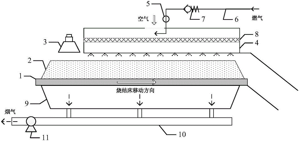
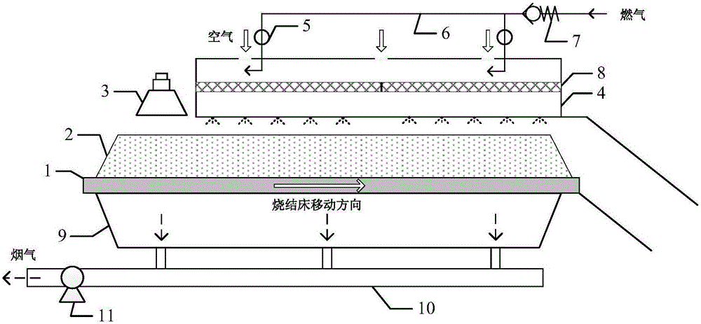
[0021] figure 1 It is a structural schematic diagram of the sintering machine provided by the present invention.

[0022] The sintering machine uses gas and solid fuel to provide heat for the sintering process, and a set of gas injection controller 5 is provided. The sintering raw material 2 moves with the sintering trolley 1, and an air inlet is set on the top of the windshield 4 above the bed of the sintering raw material 2; the gas enters the inside of the top of the windshield 4 from the gas pipeline 6 to mix with air, and the gas injection controller 5 Adjust the gas flow according to the real-time air flow to realize the control of the premixed gas / air concentration. When the sintering raw material 2 on the sintering trolley 1 passes through the igniter 3, the premixed gas / air enters the bed of the sintering raw material 2 under the action of the exhaust fan 11, and is heated and burned above the solid fuel combustion area to form secondary combustion Zone, continue to...


PUM


Abstract

A sintering machine comprises a sintering pallet, an igniter, a wind cover and an air bellow. The sintering pallet allows a sintering raw material bed layer including solid fuel to move on the sintering pallet; the igniter is located on the front portion above the sintering pallet; the air cover is located on the rear portion above the sintering pallet; the air bellow is located below the sintering pallet, used for converging smoke obtained after combustion and connected with a smoke pipeline allowing the smoke to be exhausted. The sintering machine is characterized by further comprising at least one air inlet located in the top of the wind cover, at least one fuel gas inlet located in the top of the wind cover and connected with respective fuel gas supply pipelines, and a fuel gas blowing controller arranged on at least one fuel gas supply pipeline and used for controlling the fuel gas blowing amount entering the fuel gas inlets. According to the sintering machine, the energy efficiency of the sintering process can be remarkably improved, and the universality and operation controllability of a system are improved. Based on a variable-fuel-gas-flow blowing system of the sintering machine, the problem of outstanding sintering anisotropism can be effectively relieved.

Description

technical field [0001] The invention relates to a sintering machine, more specifically to a gas injection sintering machine. Background technique [0002] Iron and steel production is the industry with the highest energy consumption in China, accounting for about 16.1% of the country's total energy consumption. Iron ore sintering is second only to ironmaking and coking processes, accounting for 9-12% of the total energy consumption in the steel industry. On the one hand, the proportion of low-grade iron ore raw materials in sinter plants is gradually increasing, and it is urgent to develop new technologies to ensure the quality of sinter ore and improve the yield of sinter ore without increasing energy consumption. On the other hand, the cost of fossil fuel coke powder commonly used in the sintering process is high and the discharge pressure is high. The use of alternative fuels can effectively alleviate the pressure of cost and discharge, but efficient and controllable enh...

Claims


Application Information

Patent Timeline
Patent Type & Authority Applications(China)
IPC IPC(8): F27B21/00F27B21/14
CPCF27B21/00F27D19/00F27D2019/004
Inventor 王秋旺程志龙郭志罡杨剑魏赏赏
Owner XI AN JIAOTONG UNIV
Why Eureka
Try Eureka