
Optical microscopy system and method for raman scattering with adapative optics

A technology of Raman microscopy and adaptive optics, applied in Raman scattering, microscopy, optical radiation measurement, etc., can solve the problems of non-compensation, loss, and real-time correction of optical alignment, etc., and achieve good signal-to-noise ratio, The effect of increasing spatial resolution

Active Publication Date: 2017-02-22
HORIBA JOBIN YVON
View PDF2 Cites 14 Cited by
  • Summary
  • Abstract
  • Description
  • Claims
  • Application Information

AI Technical Summary

Problems solved by technology

[0012] The difficulty of obtaining a satisfactory signal-to-noise ratio in state-of-the-art Raman microspectroscopy equipment is known to those skilled in the art
Therefore, any additional optical system necessarily results in losses via reflection or transmission
[0013] Some adaptive optics systems such as phase modulation systems have the disadvantage of not compensating each other: the phase shift induced on the forward path is not compensated by the phase shift of the return path
However, such systems do not allow real-time correction of all optical alignment defects

Method used


Image

  • Optical microscopy system and method for raman scattering with adapative optics
  • Optical microscopy system and method for raman scattering with adapative optics
  • Optical microscopy system and method for raman scattering with adapative optics

Examples


Embodiment Construction

[0044] device

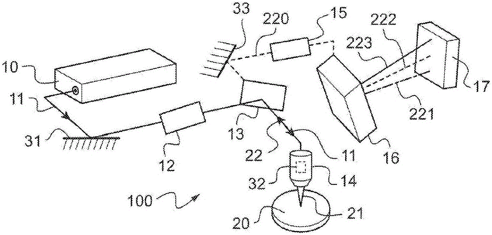
[0045] figure 1 An optical microscopy apparatus 100 of this type of Raman microspectroscopy apparatus is schematically represented. The optical microscope apparatus 100 comprises a laser source 10 adapted to emit a laser beam 11 at an excitation wavelength λ. The laser source may be selected from laser diodes, gas lasers, solid state lasers and diode pumped lasers. Depending on the material and type of laser, the emitted wavelengths can be in the far ultraviolet (244nm, 266nm), in the near ultraviolet range (325nm), in the visible range (405, 473, 532, 633, 785 and 830nm), or In the near infrared (1064nm). Depending on the type of laser source and the intended use, the laser beam 11 can be continuous or pulsed.

[0046] Advantageously, the optical system 12 is located in the optical path of the laser beam 11 between the laser source 10 and the microscope objective 14 . The optical system 12 can be used to adapt the size of the laser beam to the size of t...


PUM


Abstract

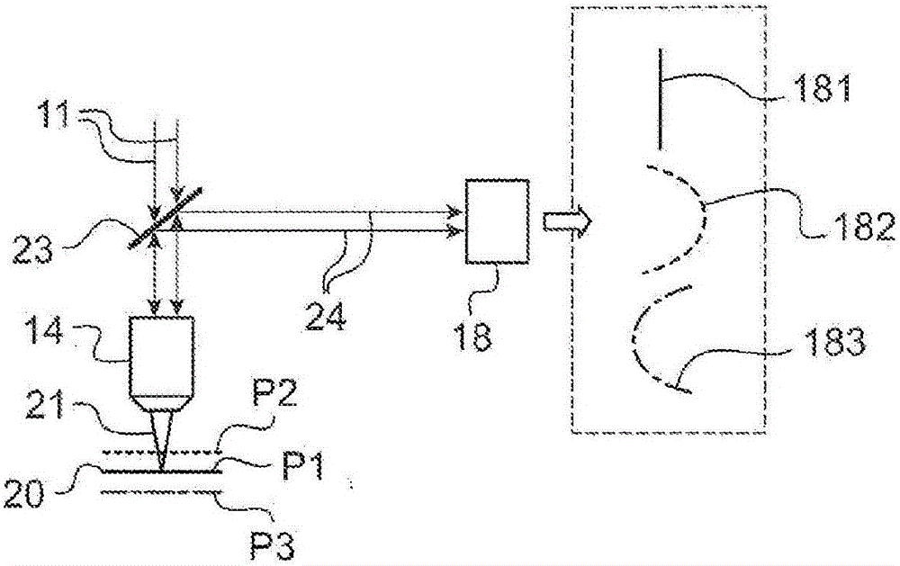
The present invention relates to a Raman scattering optical microscopy apparatus comprising a laser source (10) adapted to emit a laser beam (11) at an excitation wavelength [Lambda], a microscopy objective (14) adapted to receive the laser beam (11) and to focus the laser beam in an image plane of the microscope objective (14), the focused laser beam (21) being intended to illuminate a sample (20), an optical system adapted to collect an optical Raman scattering beam (22) and detection means (16, 17) adapted for detecting the Raman scattering beam (22) collected. More particularly, there is proposed according to the invention, a Raman scattering microscopy apparatus furthermore comprising an adaptive optics system (31, 32, 33) disposed on an optical path of the excitation laser beam (11), on an optical path of the Raman scattering beam (22) or on a common optical path of the excitation laser beam (11) and of the Raman scattering beam (22).

Description

technical field [0001] The present invention relates to the field of optical microscopy or Raman microspectroscopy for the analysis of materials or biological samples. Background technique [0002] In Raman microscopy, a sample is illuminated by an excitation beam, typically a laser beam, and light scattered at a wavelength different from that of the excitation beam is observed. Raman microscopy thus differs from conventional microscopy techniques in which light reflected, transmitted or elastically scattered by a sample at the same wavelength is observed. [0003] Raman microscopy equipment exists, which includes, for example, optical microscopes, laser sources, microscope objectives, and spectrometers. The microscope objective focuses the laser beam at a focal point on the sample and forms a scattered beam. The scattered beam includes a component called an elastic scattering component or a Rayleigh scattering component at the wavelength of the excitation laser light, and...

Claims


Application Information

Patent Timeline
Patent Type & Authority Applications(China)
IPC IPC(8): G02B21/00G01N21/65G02B21/16G01J3/44
CPCG01J3/44G01N21/65G02B21/0048G02B21/0064G02B21/0076G02B21/16G01N2021/656G01J3/0205G01N2201/06113G01N2201/063G01N2201/068G02B21/02G02B27/0025
Inventor B·狄代特D·卡特兰E·弗勒泰尔
Owner HORIBA JOBIN YVON
Learn More