Novel normal-pressure heat conducting oil furnace

A heat-conducting oil furnace and normal pressure technology, applied in the field of boilers, can solve the problems of poor thermal stability of heat-using equipment, energy waste, environmental pollution, etc., and achieve the effect of ensuring safety

Inactive Publication Date: 2017-03-08
郑新军
View PDF25 Cites 5 Cited by
  • Summary
  • Abstract
  • Description
  • Claims
  • Application Information

AI Technical Summary

Problems solved by technology

The existing heat conduction oil furnace has the following defects and deficiencies: the heating area of ​​the coil is small, the local temperature is high, and the energy consumption is increased
At the same time, because the coil is bent and the length is large, it is easy to cause the deposition of oil dirt and oil residue on the inner wall of the coil, hindering the oil circulation, and in serious cases, it is easy to cause safety hazards
The hot gas generated is directly discharged after being heated by the coil in the combustion chamber, and the waste heat of the exhaust gas cannot be used, resulting in energy waste and environmental pollution
The amount of heat-conducting oil used in the coil heating type heat-conducting oil furnace is small, and after being transmitted to the heat-consuming equipment, the temperature stability is poor, and the operation safety is poor due to the forced pressurization cycle
In addition, because the heat transfer oil contains a certain amount of water, it forms high-temperature water vapor after heating. Because the coil is bent and long, the water vapor is difficult to discharge quickly. The water vapor enters the heating equipment through the high-temperature oil pump with the heat transfer oil, which will affect the high temperature. The normal operation of the oil pump also results in poor thermal stability of the heat-using equipment, which affects the circulation speed of the heat-conducting oil in the heat-consuming equipment, thereby affecting the heating effect of the heat-consuming equipment

Method used


Image

  • Novel normal-pressure heat conducting oil furnace

Examples


Embodiment Construction

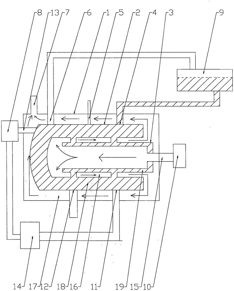
[0014] Such as figure 1 As shown, a new type of normal-pressure heat-conducting oil furnace includes a furnace body 1, a heat-conducting oil tank 2, a combustion chamber 3, a high-temperature oil pump 8, a burner 10, and a high-level oil tank 9. The heat-conducting oil tank 2 and the combustion chamber 3 are located in the furnace body 1, the high-temperature oil pump 8, burner 10 and high-level oil tank 9 are located outside the furnace body 1, the upper opening of the high-level oil tank 9 communicates with the atmosphere, and the high-level oil tank 9 contains heat transfer oil, and the heat transfer oil tank 2 is open at one end The heat-conducting oil tank 2 lies horizontally in the furnace body 1, the first oil cavity 18 is between the inner wall and the outer wall of the heat-conducting oil tank 2, the combustion chamber 3 is a hollow cylinder with one end open, and the other end of the combustion chamber 3 passes through The combustion channel 15 communicates with the ...


PUM


Abstract

The invention discloses a novel normal-pressure heat conducting oil furnace, and relates to a boiler. The novel normal-pressure heat conducting oil furnace comprises a furnace body, a heat conducting oil tank, a combustion chamber, a high-temperature oil pump, a combustor and a high-level oil tank; a first oil cavity is formed between the inner wall and the outer wall of the heat conducting oil tank; a hollow inner cavity of the combustion chamber is a flame combustion area; a second oil cavity is formed between the outer wall and the inner wall of the combustion chamber; the heat conducting oil tank surrounds the combustion chamber; a first flue for surrounding the combustion chamber is formed between the inner wall of the heat conducting oil tank and the outer wall of the combustion chamber; a second flue for surrounding the heat conducting oil tank is formed between the inner wall of the furnace body and the outer wall of the heat conducting oil tank; a smoke discharge port, an oil meter port, an exhaust port, a pressure adjusting port and an oil outlet are formed above the furnace body; the high-temperature oil pump is arranged in the oil outlet; and an oil return port communicated with the first oil cavity and a dirt discharge port are formed below the furnace body. The novel normal-pressure heat conducting oil furnace has the characteristics of normal pressure, high temperature, safety, high efficiency and energy conservation, can effectively remove water in heat conducting oil, and prevents steam from entering a circulating oil way to influence the heat efficiency of heat use equipment.

Description

technical field [0001] The invention relates to a boiler, in particular to a novel normal-pressure heat-conducting oil furnace. Background technique [0002] Heat-conducting oil furnace refers to a new type of heat energy conversion equipment whose heat-carrying medium is high-temperature heat-conducting oil (also called hot coal, heat carrier). The heated heat-conducting oil is transported to the heat-using equipment, and then returns to the heat-conducting oil furnace from the oil outlet of the heat-consuming equipment for heating, forming a complete circulation heating system. [0003] Existing heat-conducting oil furnaces generally use coiled tubes to be heated in the combustion chamber, and the medium oil in the coiled tubes is quickly circulated by means of pressurized forced circulation, and then transported to heat-consuming equipment. The fuel burns for a short time in the combustion chamber, and the hot air flows through the coil to absorb heat and is directly dis...

Claims


Application Information

Patent Timeline
Patent Type & Authority Applications(China)
IPC IPC(8): F24H7/00F24H9/00F24H9/18
CPCF24H7/00F24H9/00F24H9/18
Inventor 郑新军
Owner 郑新军
Why Eureka
Try Eureka