Multimode frequency division type injection locking frequency divider

A technology of injection locking and multi-mode frequency division, which is applied to the automatic control of power and electrical components, and can solve the problems of narrow locking range and limited number of frequency divisions.

Inactive Publication Date: 2017-03-08
TIANJIN UNIV
View PDF5 Cites 16 Cited by
  • Summary
  • Abstract
  • Description
  • Claims
  • Application Information

AI Technical Summary

Problems solved by technology

The biggest defect of the injection-locked frequency divider is that its locking range is relatively narrow, and it can only complete narrow-band work. However, considering that most wireless applications are narrow-band systems at this stage, the injection-locked frequency divider can still be effective in a specific frequency band Complete frequency division work
In addition, because the difference frequency between the harmonic and the fundamental wave is used in principle to realize the frequency division function, the frequency division ratio is usually not very large, and the frequency division number is very limited.

Method used


Image

  • Multimode frequency division type injection locking frequency divider
  • Multimode frequency division type injection locking frequency divider
  • Multimode frequency division type injection locking frequency divider

Examples


Embodiment Construction

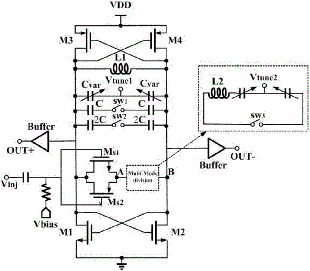
[0014] Based on the complementary MOS negative-resistance LC oscillator, the present invention injects the frequency-division signal into the oscillator through direct injection of parallel double MOS tubes, and improves the range of injection locking by means of voltage-controlled variable capacitors, switched capacitor arrays, and series peak inductance. , the frequency division ratio is changed by switching the voltage-controlled variable capacitor tuning, so as to realize the injection-locked frequency divider with low power consumption, wide locking range, and multi-mode frequency division. The present invention will be described below in conjunction with the accompanying drawings.

[0015] (1) The capacitance tuning unit improves the locking range. Such as figure 1 shown, by changing the variable capacitor C var The tuning voltage on V tune , to change the capacitance value of the resonant cavity, and then change the self-excited oscillation frequency, and realize the...


PUM


Abstract

The invention relates to a multimode frequency division type injection locking frequency divider comprising a negative resistance unit, a tuning unit, a signal injection unit and a differential output buffer, wherein the negative resistance unit is a complementary cross coupling geminate transistor negative resistance unit composed of four MOS tubes M1, M2, M3, M4; the tuning unit constitutes a resonant cavity with variable tuning frequency by a peak inductor L1, a voltage controlled variable capacitor Cvar and a 2bit switched capacitor array in a parallel manner; the signal injection unit is composed of double MOS tubes Ms1, Ms2 connected in parallel and a multimode switching unit; and a frequency division signal is injected into an oscillator in a parallel double-MOS tube direct injection mode, the tuning frequency of the resonant cavity is changed by the voltage controlled variable capacitor and the switched capacitor array, the frequency division ratio is changed, the harmonic energy is reinforced by the serially connected peak inductor L1, and the locking range is expanded.

Description

technical field [0001] The invention belongs to the technical field of integrated circuit design and relates to a frequency divider. Background technique [0002] With the rapid development of science and technology and people's increasing demand for high-performance portable electronic products, wireless communication technology exists in almost all electronic products, including mobile communication, satellite communication, wireless local area network, radio frequency identification, ultra-wideband technology, etc. . In modern communication systems, radio frequency wireless transceiver front-end plays a pivotal role. As the requirements for information acquisition, transmission and processing continue to increase, the most critical challenge is to obtain a stable local oscillator, and a phase-locked loop frequency synthesizer based on precise phase modulation has become a good choice. [0003] The two most important modules in the phase-locked loop frequency synthesizer...

Claims


Application Information

Patent Timeline
Patent Type & Authority Applications(China)
IPC IPC(8): H03L7/18
CPCH03L7/18
Inventor 张为刘建涛高婉航
Owner TIANJIN UNIV
Why Eureka
Try Eureka