
Exhaust gas treating device, temperature raising method of catalyst, regeneration method of honeycomb structure, and ash removing method

一种废气处理装置、蜂窝结构体的技术,应用在排气处理装置的电控、催化剂载体、物理/化学过程催化剂等方向,能够解决产生煤烟等问题,达到容易升温、缩小大小、压力损失的上升小的效果

Active Publication Date: 2017-03-15
NGK INSULATORS LTD
View PDF6 Cites 5 Cited by
  • Summary
  • Abstract
  • Description
  • Claims
  • Application Information

AI Technical Summary

Problems solved by technology

However, the direct-injection gasoline engine has good fuel consumption, but there is a problem that a lot of soot is generated when the engine is started and accelerated.

Method used


Image

  • Exhaust gas treating device, temperature raising method of catalyst, regeneration method of honeycomb structure, and ash removing method
  • Exhaust gas treating device, temperature raising method of catalyst, regeneration method of honeycomb structure, and ash removing method
  • Exhaust gas treating device, temperature raising method of catalyst, regeneration method of honeycomb structure, and ash removing method

Examples


Embodiment 1

[0146] 13 parts by mass of a pore-forming material, 35 parts by mass of a dispersion medium, 6 parts by mass of an organic binder, and 0.5 parts by mass of a dispersant were added to 100 parts by mass of a cordierite chemical raw material, mixed and kneaded to prepare a base earth. As cordierite-forming raw materials, alumina, aluminum hydroxide, kaolin, talc, and silica are used. Water was used as a dispersion medium, coke with an average particle diameter of 1 to 10 μm was used as a pore-forming material, hydroxypropylmethylcellulose was used as an organic binder, and ethylene glycol was used as a dispersant. The particle diameter and amount of the pore-forming material are controlled, thereby controlling the pore diameter and porosity of the partition wall.

[0147] Next, the kneaded material is extruded using a predetermined die so that a formed honeycomb body having partition walls and partition walls can be obtained to obtain a cylindrical formed honeycomb body.

[014...

Embodiment 2~11

[0183] Except for the changes shown in Table 1, in the same manner as in Example 1, "overall system length", "pressure loss at rated operation", "purification rate", "PM capture" and "after driving 160,000 km Amount of ash accumulation". The results are shown in Table 2.

reference example 1

[0185] against Figure 7 For an exhaust gas treatment device such as the exhaust gas treatment device 300 shown, the "total system length", "pressure loss during rated operation", "purification rate", "PM capture" and "traveling The amount of ash accumulated after 160,000km" evaluation. The results are shown in Table 2.

[0186] The exhaust gas treatment device 300 includes: a tank body 120 in which an exhaust gas inlet 121 and an outlet port 127 are formed; and a filter group 60 including three honeycomb structures housed in the tank body 120 . The filter group 60 is composed of a first honeycomb structure 61 , a second honeycomb structure 62 , and a third honeycomb structure 63 arranged sequentially from the exhaust gas inlet 121 side of the tank body 120 . Furthermore, these honeycomb structures 61 , 62 , and 63 are all cylindrical, and the diameter of the first honeycomb structure 61 is 80 mm. In addition, in Figure 7 In , the reference sign X represents the length of...


PUM


Abstract

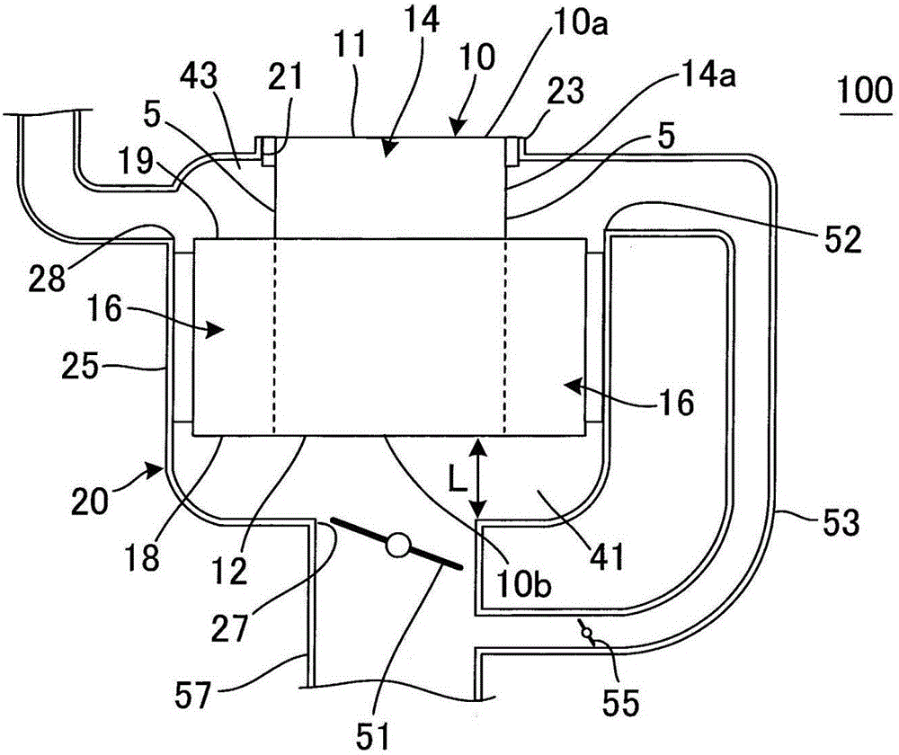
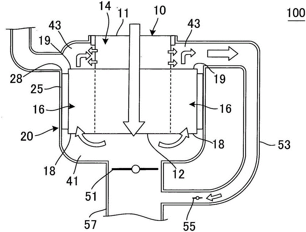
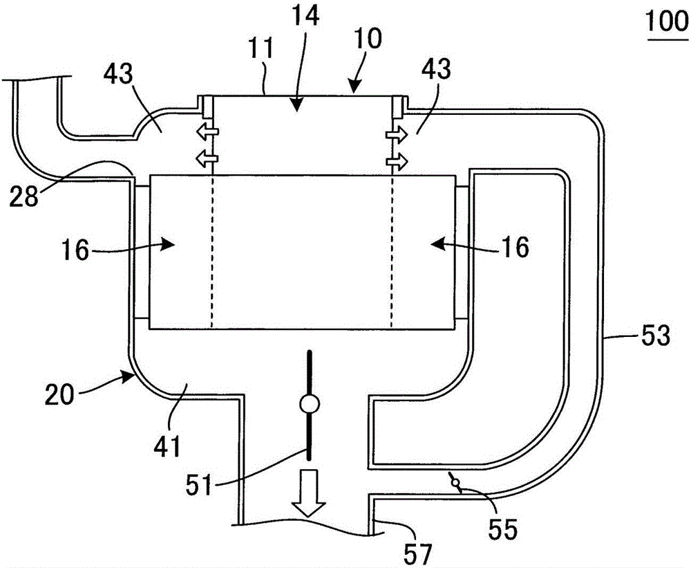
An exhaust gas treating device includes a honeycomb structure including an inner honeycomb structure body, an outer honeycomb structure body disposed at a position which surrounds a part of a circumference of the inner honeycomb structure body and is away from the inner inflow end face of the inner honeycomb structure body, and plugging portions arranged in parts of cells; a can member which stores the honeycomb structure and has an inlet and a second outlet for an exhaust gas; and an opening / closing valve to open and close the second outlet of the can member.

Description

technical field [0001] The present invention relates to an exhaust gas treatment device, a method for raising the temperature of a catalyst using the exhaust gas treatment device, a method for regenerating a honeycomb structure, and a method for removing ash. In more detail, it relates to an exhaust gas treatment device that can be reduced in overall size, is easy to raise temperature, is difficult to rapidly cool, and has a small increase in pressure loss, a method for raising the temperature of a catalyst using the exhaust gas treatment device, a method for regenerating a honeycomb structure, and removal of ash method. Background technique [0002] Conventionally, in internal combustion engines such as gasoline engines and diesel engines, generation of combustion residues generated during fuel combustion has been a problem. Therefore, from the viewpoint of the atmospheric environment, it is required to remove the toxic components contained in the exhaust gas without causi...

Claims


Application Information

Patent Timeline
Patent Type & Authority Applications(China)
IPC IPC(8): F01N3/035F01N3/022F01N3/023F01N3/20B01J35/04B01D53/86B01D46/24
CPCB01D46/24B01D53/86F01N3/0217F01N3/022F01N3/023F01N3/0232F01N3/0233F01N3/0235F01N3/035F01N3/2006F01N2240/00B01D46/247B01D46/2459B01D46/2474B01D46/2484B01D46/2482B01D46/2476B01J35/56F01N9/002F01N3/031F01N2240/36F01N2330/06F01N13/0097F01N13/0093B01D46/0087F01N3/0222F01N2250/02Y02T10/40B01D46/82B01D46/2455B01D46/2422B01D46/4236B01D2279/30
Inventor 青木崇志
Owner NGK INSULATORS LTD
Learn More