
Liquid Piston Work Recovery Pulse Tube Refrigeration System and Application of Liquid Piston in it

A liquid piston and pulse tube refrigeration technology, which is applied in refrigeration and liquefaction, refrigerators, lighting and heating equipment, etc., can solve the problems of low efficiency of refrigerators, sound power dissipation, and difficulty in implementation, and achieve long life and high efficiency , the effect of compact structure

Active Publication Date: 2018-10-30
TECHNICAL INST OF PHYSICS & CHEMISTRY - CHINESE ACAD OF SCI
View PDF7 Cites 0 Cited by
  • Summary
  • Abstract
  • Description
  • Claims
  • Application Information

AI Technical Summary

Problems solved by technology

To obtain a large cooling capacity in the liquid nitrogen temperature zone and obtain an extremely low temperature below 10K, it is necessary to increase the input power of the pulse tube refrigerator, and the sound power consumed in the phase modulation device is also significantly increased, making the system efficiency low
In addition, for low-frequency pulse tube refrigerators below 10K, the required phase modulation angle is also significantly increased, and the phase modulation system also faces the problem of insufficient phase modulation capability
Therefore, in view of the main problems in the development of pulse tube refrigerators, a feasible method is to explore power recovery and phase modulation pulse tube refrigerators, which can simultaneously solve the problems of sound power dissipation and insufficient phase modulation capabilities.
[0005] In the existing power recovery phase modulation pulse tube refrigerator, the good capacitive reactance and inductive reactance effect of the adsorber has been used to replace the gas storehouse and inertia tube in the traditional pulse tube refrigerator, so as to achieve the minimum required for the refrigerator to work. Good phase shift, but this device cannot solve the problem of the dissipation of sound work in the pulse tube in the phase modulation device, so the efficiency of the refrigerator is low; there are also pressure fluctuations that rely on the inertia of the moving mass module, inertia tube or valve resistance to form a phase lead The impedance boundary adjustment of the volumetric flow rate increases the ability of phase modulation, but the system still includes devices such as small hole air reservoirs, the system is complex and the sound work consumed by the phase modulation device has not been completely eliminated; and by setting the vessel to 1 / The 4-wavelength long neck tube adjusts the phase between the internal pressure wave and the volume flow of the refrigerator, eliminating the need for the original passive or active phase adjustment device
But this method requires that the long-necked tube has a 1 / 4 wavelength, and the temperature, frequency and pressure of the refrigerator will affect the wavelength, making this invention more difficult to realize

Method used


Image

  • Liquid Piston Work Recovery Pulse Tube Refrigeration System and Application of Liquid Piston in it
  • Liquid Piston Work Recovery Pulse Tube Refrigeration System and Application of Liquid Piston in it
  • Liquid Piston Work Recovery Pulse Tube Refrigeration System and Application of Liquid Piston in it

Examples


Embodiment 1

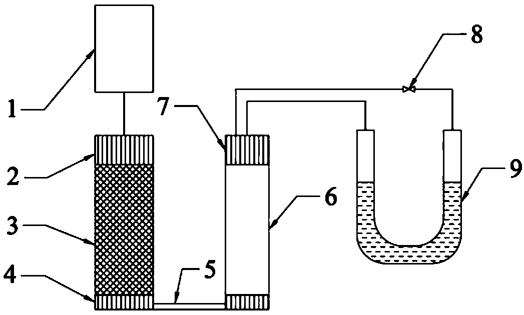
[0032] Such as figure 1 Shows the structure of the liquid piston work recovery type pulse tube refrigeration system in Embodiment 1 of the present invention: it includes a pressure wave generator 1 connected in sequence, for example, a VM type low frequency generator, a room temperature end heat exchanger 2, and a cold accumulator 3. Cold end heat exchanger 4 , pulse tube 6 , pulse tube hot end heat exchanger 7 and phase modulation device 9 . Among them, the pressure wave generator 1 is connected to the heat exchanger 2 at the room temperature end through a connecting pipe, the heat exchanger 4 at the cold end is connected to the pulse tube 6 through the cold head connecting pipe 5, and the heat exchanger 7 at the hot end of the pulse tube is connected to the phase modulation device 9 The inlet of (U-shaped tube filled with liquid mercury) is connected through a connecting pipeline, and the outlet of the phasing device 9 is communicated with the hot end heat exchanger 7 of the...

Embodiment 2

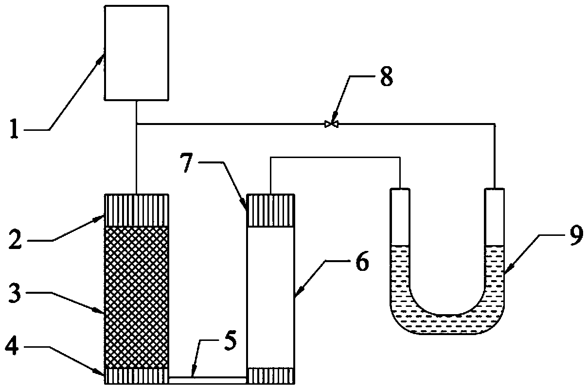
[0035] Such as image 3 The structure of the liquid piston work recovery type pulse tube refrigeration system in Embodiment 2 of the present invention is shown, which is basically the same as in Embodiment 1, the only difference being that the outlet of the phase modulation device 9 passes through the pipeline and the pressure wave generator 1 It is connected to the pipeline between the heat exchangers at the room temperature end, and the pipeline is provided with a resistance adjustment device, such as a regulating valve 8, and the liquid in the U-shaped tube is gallium-indium alloy, and the other conditions remain unchanged. Thereby realizing the recovery of work and the adjustment of the phase of this refrigeration system. During the working process of the pulse tube refrigeration system, controlling the opening of the regulating valve 8 can conveniently adjust the stiffness of the gas working medium above the liquid on the right side of the U-shaped tube, so that the work ...


PUM


Abstract

The invention discloses a liquid piston work recycling type pulse pipe refrigerating system. The system comprises a pressure wave generator, a room temperature end heat exchanger, a cold accumulator, a cold end heat exchanger, a pulse pipe, a pulse pipe heat end heat exchanger and a phase adjusting device, all of which are sequentially connected. An outlet of the phase adjusting device is connected with a pipeline between the pulse pipe heat end heat exchanger or the pressure wave generator and the room temperature end heat exchanger, and a liquid piston is arranged in the phase adjusting device. In the liquid piston work recycling type pulse pipe refrigerating system, the liquid piston is arranged in the phase adjusting device of the pulse pipe refrigerating system, adjustment on the phase position of the refrigerating system is achieved, and work recycling can be achieved as well.

Description

technical field [0001] The present invention relates to a pulse tube refrigeration device. More specifically, it relates to a liquid piston work recovery type pulse tube refrigeration system using a liquid piston for work recovery and the application of the liquid piston therein. Background technique [0002] The pulse tube refrigerator was first invented by Gifford and Longswoth in the United States. It consists of a regenerator, a pulse tube, a hot-end heat exchanger, a cold-end heat exchanger, and a phase adjustment device. Since the refrigerator does not move at low temperatures The components avoid the problems of sealing, wear and vibration at low temperature, so they have the advantages of compact structure, low vibration, long life, etc., and have a very wide range of applications in space technology, superconducting electronics, infrared detection, low temperature biomedicine, etc. Application prospects. [0003] Although the attractiveness of the pulse tube refri...

Claims


Application Information

Patent Timeline
Patent Type & Authority Patents(China)
IPC IPC(8): F25B9/14
CPCF25B9/145
Inventor 潘长钊周远王俊杰
Owner TECHNICAL INST OF PHYSICS & CHEMISTRY - CHINESE ACAD OF SCI
Learn More