Millimeter-wave microstrip array antenna

A technology of microstrip array and array antenna, applied in antenna, antenna coupling, antenna array and other directions, can solve the problems of large loss, low power, low gain, etc., achieve low VSWR, small mutual coupling influence, and ensure amplitude and phase performance Effect

Inactive Publication Date: 2017-03-15
ANHUI SUN CREATE ELECTRONICS
View PDF0 Cites 21 Cited by
  • Summary
  • Abstract
  • Description
  • Claims
  • Application Information

AI Technical Summary

Problems solved by technology

At present, traditional microstrip antennas usually use circular or rectangular patch slots to

Method used


Image

  • Millimeter-wave microstrip array antenna
  • Millimeter-wave microstrip array antenna
  • Millimeter-wave microstrip array antenna

Examples


Embodiment Construction

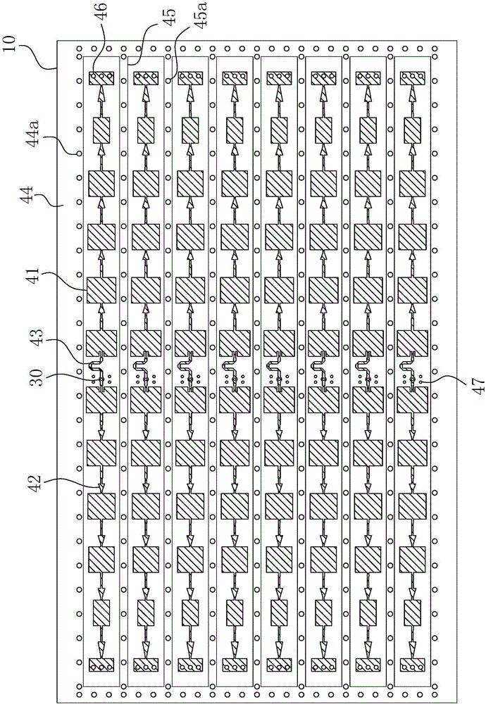
[0037] For ease of understanding, here we take the microstrip array transmitting antenna of the 3D traffic management radar system as an example. Since the feed network adopts the structure of microstrip divided by n, n must be a positive integer greater than 1; here n=8 In conjunction with the accompanying drawings, the specific implementation structure and work flow of the present invention are described as follows:

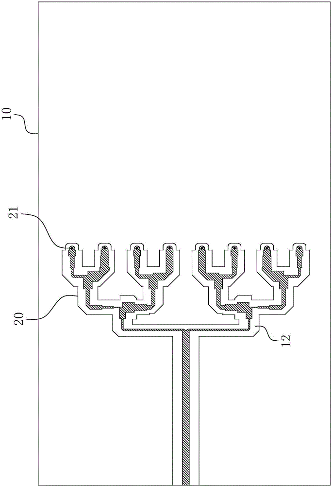
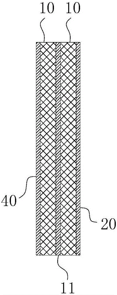
[0038]The antenna consists of a double-layer dielectric board 10 sandwiching a metal ground 11 , a patch array antenna 40 arranged on one side of the dielectric board 10 , and a feed network 20 arranged on the other side of the dielectric board 10 . image 3 It can be seen from the figure that the specific layout position of the double-layer dielectric board 10 relative to the patch array antenna and the feed network 20 is: the two-layer dielectric board 10 is bonded together by lamination process, and a layer of metal ground 11 is interposed in the middle. One...


PUM

PropertyMeasurementUnit
Thicknessaaaaaaaaaa

Abstract

The invention relates to the technical field of antennas, in particular to a millimeter-wave microstrip array antenna. The millimeter-wave microstrip array antenna comprises a dielectric plate, patch array antennas and a feed network, wherein the dielectric plate comprises a double-layer plate body, and a metal ground is clamped between the two layers of the double-layer plate body; the feed network is a one-to-n path of T-type power dividing circuit, each branch port of the feed network is provided with a feed point, the patch array antennas are arranged in n columns, and central symmetry points of the patch array antennas are provided with coaxial feed probes which penetrate the dielectric plate vertically so as to connect the feed points with the patch array antenna; and on the same column of the patch array antennas, the coaxial feed probes are directly connected between relatively proximate microstrip patches on a group of patch units, and are interconnected between relatively proximate microstrip patches on another group of patch units by means of 180-degree phase shifters. The millimeter-wave microstrip array antenna has the advantages of high gain, low sidelobe and miniaturization, and can effectively realize the high integration and miniaturization requirements of the whole antenna structure.

Description

technical field [0001] The invention belongs to the technical field of antennas, and in particular relates to a millimeter-wave microstrip array antenna. Background technique [0002] The antenna is an important radio equipment in the communication system, and its performance will directly affect the performance of the radio equipment. With the continuous development and improvement of wireless communication and radar systems, performance requirements such as light weight, small size, simple fabrication, easy conformality, wide frequency band and low cost have been put forward for antenna performance. Microstrip antennas have attracted people's attention precisely because they meet the above requirements, and their applications have become more and more extensive in recent years. However, the unit gain of the microstrip antenna is generally 6dBi to 8dBi, so the microstrip array antenna composed of microstrip patch units is commonly used to obtain greater gain or achieve spe...

Claims


Application Information

Patent Timeline
IPC IPC(8): H01Q1/38H01Q1/50H01Q1/52H01Q1/48H01Q21/00
CPCH01Q1/523H01Q1/48H01Q21/0006H01Q21/065
Inventor 李霞孙浩胡卫东侯艳茹高静袁士涛吴莹莹
Owner ANHUI SUN CREATE ELECTRONICS
Why Eureka
Try Eureka