
Ingot casting method capable of reducing red edge width of polycrystalline silicon ingot, polycrystalline silicon ingot and crucible for polycrystalline silicon ingot casting

A technology for polycrystalline silicon ingots and polycrystalline silicon wafers, which is applied to the growth of polycrystalline materials, chemical instruments and methods, crystal growth, etc. Edge width, improved minority carrier lifetime, and improved quality

Active Publication Date: 2017-03-22
JIANGXI SAI WEI LDK SOLAR HI TECH CO LTD
View PDF16 Cites 3 Cited by
  • Summary
  • Abstract
  • Description
  • Claims
  • Application Information

AI Technical Summary

Problems solved by technology

The method of reducing the width of the side red edge by widening the crucible has the following disadvantages: 1. The width of the red edge is reduced by increasing the thickness of the cut side skin, which will affect the yield of silicon ingots and increase the cost of casting ingots; 2. The crucible The widened size is limited by the ingot furnace and other accessories, and the increased width is limited
The method of adopting a high-purity crucible has the following disadvantages: 1. The high-purity crucible is expensive, which increases the purchase cost of the crucible

Method used

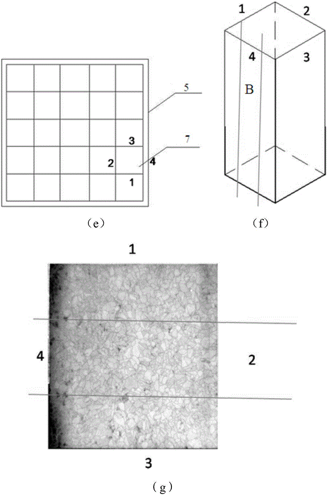

Image

  • Ingot casting method capable of reducing red edge width of polycrystalline silicon ingot, polycrystalline silicon ingot and crucible for polycrystalline silicon ingot casting
  • Ingot casting method capable of reducing red edge width of polycrystalline silicon ingot, polycrystalline silicon ingot and crucible for polycrystalline silicon ingot casting
  • Ingot casting method capable of reducing red edge width of polycrystalline silicon ingot, polycrystalline silicon ingot and crucible for polycrystalline silicon ingot casting

Examples


Embodiment 1

[0109] An ingot casting method for reducing the width of the red edge of a polycrystalline silicon ingot, comprising the following steps:

[0110] (1) Provide a crucible with an inner diameter of 840*840mm and a height of 480mm, spray a layer of silicon nitride coating on the side wall and base of the crucible, and let it dry naturally;

[0111] (2) Cut the high-purity graphite paper with a thickness of 200 μm into four rectangles whose specifications are respectively 780*300mm;

[0112] (3) Evenly smear one layer of high-purity silica sol on the high-purity graphite paper as a binding agent; four pieces of high-purity graphite paper coated with silica sol are attached to the four side walls of the crucible respectively to form a barrier layer;

[0113] (4) Install the seed crystal in the crucible, then fill the silicon material above the seed crystal, then control the temperature so that the silicon material melts from top to bottom, and after the silicon material melts to th...

Embodiment 2

[0118] An ingot casting method for reducing the width of the red edge of a polycrystalline silicon ingot, comprising the following steps:

[0119] (1) Provide a crucible with an inner diameter of 840*840mm and a height of 480mm, spray a layer of silicon nitride coating on the side wall and base of the crucible, and let it dry naturally;

[0120] (2) Provide nine*four rectangular high-purity graphite sheets with a thickness of 2mm and a length and width of 260*100mm;

[0121] (3) On nine pieces of high-purity graphite sheets, smear one layer of high-purity silica sol evenly as the binding agent respectively; High-purity graphite sheets coated with silica sol are also pasted on the other three side walls to form a barrier layer;

[0122] (4) Install the seed crystal in the crucible, then fill the silicon material above the seed crystal, then control the temperature so that the silicon material melts from top to bottom, and after the silicon material melts to the position of the...

Embodiment 3

[0127] An ingot casting method for reducing the width of the red edge of a polycrystalline silicon ingot, comprising the following steps:

[0128] (1) Provide a crucible with an inner diameter of 840*840mm and a height of 480mm, spray a layer of silicon nitride coating on the side wall and base of the crucible, and let it dry naturally;

[0129] (2) Provide two*four rectangular high-purity molybdenum sheets with a thickness of 50μm and a length and width of 390*300mm;

[0130] (3) On two high-purity molybdenum sheets, smear one layer of high-purity silica sol evenly as binding agent respectively; Two high-purity molybdenum sheets that are coated with silica sol are spliced ​​and attached on one side wall of the crucible, similarly, High-purity molybdenum sheets coated with silica sol are also pasted on the other three side walls of the crucible to form a barrier layer;

[0131] (4) setting a layer of silicon nitride layer on the barrier layer by spraying, the thickness of the...


PUM

PropertyMeasurementUnit
thicknessaaaaaaaaaa
thicknessaaaaaaaaaa
thicknessaaaaaaaaaa

Abstract

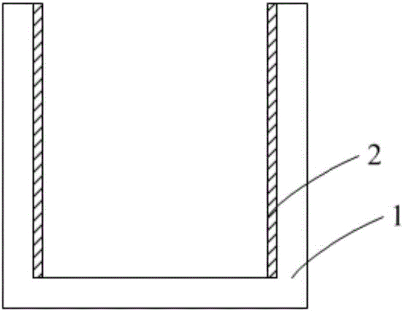
The invention provides an ingot casting method capable of reducing the red edge width of a polycrystalline silicon ingot. The method includes the following steps that a crucible is provided, wherein the crucible comprises a base and a side wall extending upwards from the base, the base and the side wall define a containing space together, a barrier layer is arranged on the surface, facing the containing space, of the side wall, a high-purity sheet with the melting point higher than that of silicon and the purity being 99.99% or above is selected as the barrier layer, and the material of the high-purity sheet is selected from at least one of a transition metal elementary substance, a transition metal compound, graphite, an aluminum compound and a boron compound; then, a silicon material in a molten state is placed in the crucible; the temperature in the crucible is controlled to rise gradually in the upward direction perpendicular to the bottom of the crucible to form a temperature gradient, and thus the silicon material in the molten state starts to crystallize; after the silicon material crystallizes completely, the polycrystalline silicon ingot is obtained through annealing cooling. By arranging the barrier layer on the side wall of the crucible, impurities in the crucible can be prevented from entering the silicon ingot / silicon melt, the red edge width of the silicon ingot is reduced, and the minority carrier lifetime of the polycrystalline silicon ingot is prolonged.

Description

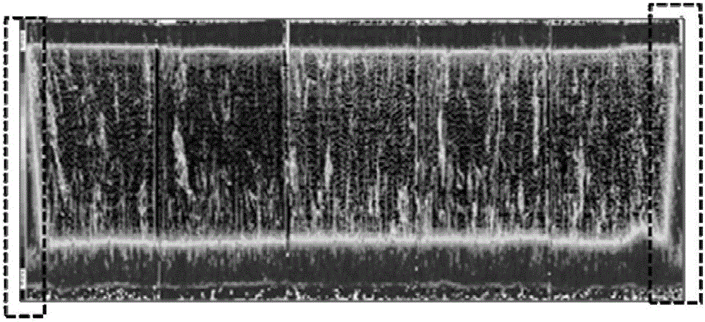
technical field [0001] The invention relates to the field of polycrystalline silicon ingot casting, in particular to an ingot casting method for reducing the width of the red edge of a polycrystalline silicon ingot, a polycrystalline silicon ingot and a crucible for polycrystalline silicon ingot casting. Background technique [0002] In the existing polycrystalline ingot casting process, impurities in the crucible, especially metal impurities, will diffuse into the silicon ingot at high temperature, resulting in a low minority carrier lifetime of less than 2 μs in the silicon ingot near the side wall of the crucible, usually Call this region of low birthrates the red edge. like figure 1 The dotted frame area in is the red edge. After the red edge is made into a battery sheet, a black edge phenomenon will appear under the EL (electroluminescence) or PL (photoluminescence) test. Black edges will lead to low photoelectric conversion efficiency, which will affect the performa...

Claims


Application Information

Patent Timeline
Patent Type & Authority Applications(China)
IPC IPC(8): C30B28/06C30B29/06
CPCC30B28/06C30B29/06C30B35/002
Inventor 陈红荣徐云飞胡动力
Owner JIANGXI SAI WEI LDK SOLAR HI TECH CO LTD
Learn More