A Reconfigurable Optically Controlled Phased Array Radar Receiver Based on Optical Switching

An optically controlled phased array and optical switching technology, applied in radio wave measurement systems, instruments, etc., can solve the problems of restricting the application of phased array antennas, narrowing the working bandwidth, and raising the level of side lobes, so as to suppress side lobes. effect, reduces the limitation of aperture transit time, has the effect of signal processing

Active Publication Date: 2019-01-04
ZHEJIANG UNIV
View PDF6 Cites 0 Cited by
  • Summary
  • Abstract
  • Description
  • Claims
  • Application Information

AI Technical Summary

Problems solved by technology

However, there are still many problems in the full electronic control of the phased array antenna unit. The main reason is that the phased array antenna can only scan in a relatively narrow signal bandwidth due to the limitation of the aperture transit time, which limits its wideband and Wide-angle scanning performance, which severely restricts the application of phased array antennas in complex environments and high-performance fields
[0003] There are many methods for antenna multi-beam formation, such as Blass method, Buter multi-beam matrix method, all-digital multi-beam (DBF) method and sub-antenna array method, etc. For the common DBF and sub-antenna array methods in receiving antennas, The advantage of the all-digital multi-beam method is high performance and easy to realize continuous sliding scanning. The disadvantage is that the number of channels is large and the cost is high. The advantage of the sub-antenna array method is that it reduces complexity and saves money. Flat elevation and narrowing of operating bandwidth

Method used


Image

  • A Reconfigurable Optically Controlled Phased Array Radar Receiver Based on Optical Switching
  • A Reconfigurable Optically Controlled Phased Array Radar Receiver Based on Optical Switching
  • A Reconfigurable Optically Controlled Phased Array Radar Receiver Based on Optical Switching

Examples


Embodiment Construction

[0026] In order to describe the present invention more specifically, the technical solutions of the present invention will be described in detail below in conjunction with the accompanying drawings and specific embodiments.

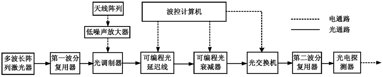
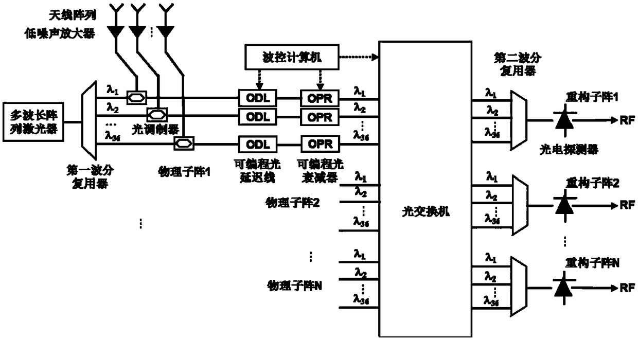
[0027] Such as figure 1 As shown, the reconstructed optical phased array radar receiver based on optical switching includes multi-wavelength array laser, first wavelength division multiplexer, optical modulator, programmable optical delay line, programmable optical attenuator, all-optical A wavelength switch, a second wavelength division multiplexer, a photodetector, an antenna array, a low noise amplifier, and a wave control computer; wherein a multi-wavelength array laser, a first wavelength division multiplexer, an optical modulator, a programmable optical delay line, A programmable optical attenuator, an all-optical wavelength switch, a second wavelength division multiplexer, and a photodetector form an optical radio frequency link; the antenna array ...


PUM


Abstract

The present invention discloses a reconstruction light-controlled phased array radar receiver based on optical switching, which comprises an antenna array, a low noise amplifier, a wave control computer, a laser, a first wavelength division multiplexer, an optical modulator, a programmable light delay line, a programmable optical attenuator, an all-optical wavelength switch, a second wavelength division multiplexer and a photodetector. The invention organically combines the wavelength division multiplexing method and the all-optical wavelength switching method, and on the basis of the advantages of the traditional light-controlled phased array radar, the dynamic reconstruction of the subarray is realized, and simultaneous multi-target full-range tracking that the traditional light control phased array radar is unable to achieve is achieved; and the radar receiver is simple and easy to operate, and reliable in performance and has cost advantages.

Description

technical field [0001] The invention relates to the technical field of optically controlled phased array radar, in particular to a reconstructed optically controlled phased array radar receiver based on optical switching. Background technique [0002] Compared with the traditional mechanical scanning radar antenna, the phased array antenna realized by modern electronic technology has great advantages in terms of response speed, target update rate, multi-target tracking ability, resolution, and versatility. The phased array antenna uses a specific feeding method, intelligent control and adjustment of the amplitude and phase of the array element to make the beamforming non-inertial and flexible scanning, thereby greatly improving the information acquisition and update rate. In a phased array antenna system, the beam scanning is formed by adjusting the phase relationship between the radiating elements, so the signal distribution method required to obtain the necessary phase rel...

Claims


Application Information

Patent Timeline
Patent Type & Authority Patents(China)
IPC IPC(8): G01S7/484G01S7/491
CPCG01S7/484G01S7/4911
Inventor 祝艳宏金晓峰金向东余显斌郑史烈池灏章献民
Owner ZHEJIANG UNIV
Why Eureka
Try Eureka