
Mode-based synchronous wavefront sensorless adaptive optical system

An adaptive optics and mode technology, applied in optics, optical components, instruments, etc., can solve the problems of increasing the constraints of the basis function of the aberration mode, increasing the difficulty of mathematical solution of the system, and the slope function is not necessarily orthogonal, etc., to achieve Reduce computational complexity and memory requirements, improve time-domain correlation, and reduce delay effects

Active Publication Date: 2017-03-22
INST OF OPTICS & ELECTRONICS - CHINESE ACAD OF SCI
View PDF7 Cites 8 Cited by
  • Summary
  • Abstract
  • Description
  • Claims
  • Application Information

AI Technical Summary

Problems solved by technology

Therefore, in order to solve the delay uncertainty problem of the above-mentioned system method, the core is to orthogonalize the slope correlation matrix of the aberration mode, and find the basis function orthogonal to the basis function of the aberration mode and its slope function. Usually, the basis function of the aberration mode The function is orthogonal, but its slope function is not necessarily orthogonal, so this method increases the constraints of the basis function of the aberration mode, which increases the difficulty of mathematical solution for system implementation

Method used


Image

  • Mode-based synchronous wavefront sensorless adaptive optical system
  • Mode-based synchronous wavefront sensorless adaptive optical system
  • Mode-based synchronous wavefront sensorless adaptive optical system

Examples


Embodiment Construction

[0053] The present invention will be further described below in conjunction with the accompanying drawings and implementation examples. The main condition of the implementation example, the incident wavefront aberration is composed of 18th-order Zernike polynomials except translation and tilt aberrations, that is, the aberration mode basis function F i (x,y) is Z i (x, y) (i=3~20), its coefficient follows the kolmogrov power spectrum and is randomly generated. When dynamic aberration correction is applied, the wind speed is 3m / s, and the interference intensity D / r=5.

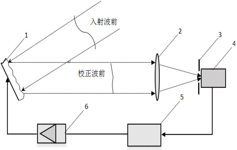
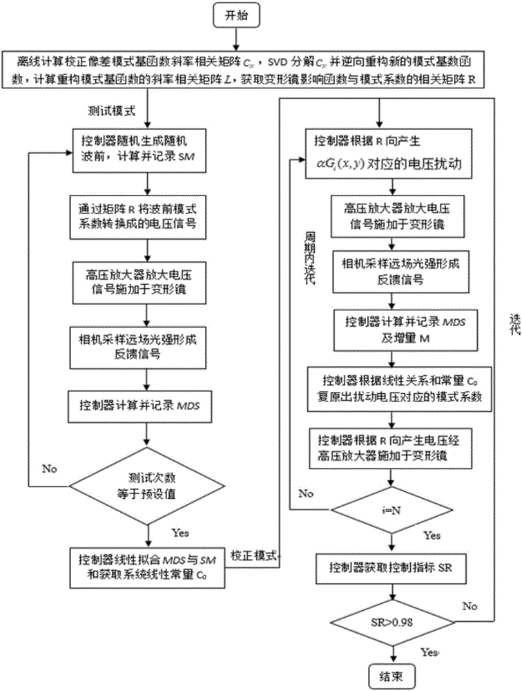
[0054] figure 1 It is the system composition of the present invention, which is mainly composed of a wavefront correction unit deformable mirror 1, a focusing lens 2, an obscuring pinhole 3, a far-field detection camera 4, a controller 5 and a high-voltage amplifier 6. figure 2 It is a flowchart of the system aberration correction algorithm, which is mainly divided into offline data processing and real-time ...


PUM


Abstract

The invention relates to a mode-based synchronous wavefront sensorless adaptive optical system, consisting of a focal plane photoelectric detection camera, a controller, a high-voltage amplifier and a wavefront aberration correction unit (deformable mirror). A disturbance voltage related to an aberration mode is applied to the deformable mirror once, the camera measures focal plane far field light intensity, the controller calculates second-order central moment MDS, and according to an approximate linear relation between the second-order central moment MDS of far field light intensity distribution and a mean value SM of the square of incident wavefront aberration slopes, a coefficient of the aberration mode corresponding to the disturbance voltage contained in wavefront distortion is solved; and a relation matrix of a deformable mirror response function and aberration modes is utilized to form a voltage signal, and the voltage signal is amplified by the high-voltage amplifier and is applied to the deformable mirror, thereby completing effective correction of the aberration of the mode, and realizing a system synchronous correction iteration mechanism of one-time disturbance and one-time correction; and the mode-based synchronous wavefront sensorless adaptive optical system provided by the invention shortens delay of iteration of two adjacent times of aberration correction, and improves a capability of correcting dynamic aberrations of a system.

Description

technical field [0001] The present invention is a wavefront-free adaptive optics system, in particular to an adaptive optics system based on a universal mode and a synchronous iterative mechanism suitable for dynamic wavefront correction, which is suitable for optical communications, microscopes, laser beam purification, human Wavefront aberration correction in applications such as eye imaging. Background technique [0002] Adaptive Optics (AO) is a technology developed in the 1980s. Adaptive optics systems are divided into adaptive optics systems with wavefront sensing and adaptive optics systems without wavefront sensing according to whether there is a dedicated wavefront detector; among them, adaptive optics systems without wavefront sensing (WFSless AO) is widely used in wavefront phase discontinuity and some special applications such as laser nuclear fusion device, confocal microscope, fiber coupling, laser phase control, optical clamp, optical tracking, extended targe...

Claims


Application Information

Patent Timeline
Patent Type & Authority Applications(China)
IPC IPC(8): G02B27/00
CPCG02B27/0012
Inventor 文良华杨平王帅陈善球许冰
Owner INST OF OPTICS & ELECTRONICS - CHINESE ACAD OF SCI
Learn More