Differential architecture storage unit for improving NBTI (Negative Bias Temperature Instability) effect of P-type NVM (Non Volatile Memory)

A storage unit and memory technology, applied in static memory, read-only memory, information storage, etc., can solve problems such as device performance degradation, and achieve the effects of improved stability, reduced power consumption, increased reliability and storage life

Active Publication Date: 2017-03-22
SUZHOU KUANWEN ELECTRONICS SCI & TECH
View PDF13 Cites 10 Cited by
  • Summary
  • Abstract
  • Description
  • Claims
  • Application Information

AI Technical Summary

Problems solved by technology

This NBTI effect, which leads to device degradation, becomes more pronou

Method used


Image

  • Differential architecture storage unit for improving NBTI (Negative Bias Temperature Instability) effect of P-type NVM (Non Volatile Memory)
  • Differential architecture storage unit for improving NBTI (Negative Bias Temperature Instability) effect of P-type NVM (Non Volatile Memory)
  • Differential architecture storage unit for improving NBTI (Negative Bias Temperature Instability) effect of P-type NVM (Non Volatile Memory)

Examples


Embodiment 1

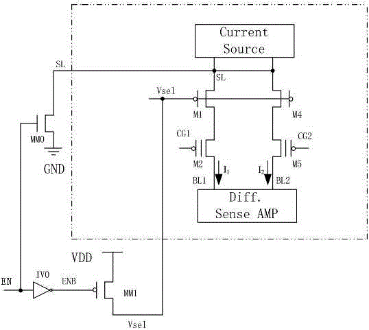
[0056] figure 1 It is based on the traditional floating gate type pFlash storage unit, and adopts a differential architecture on the basis of it, and adds an NBTI recovery circuit at the same time.

[0057] see figure 1 As shown, the basic module is a floating gate type pFlash memory cell. The uppermost module is the constant current source module Current Sourced, which is usually realized by a MOS current source operating in the saturation region. Its advantage is that it is compatible with standard processes and the current is stable. The PMOS transistor M1 and the PMOS transistor M4 are selection transistors, the gate of which is connected to the gate voltage Vsel of the word line, the source is connected to the above-mentioned constant current source module, the drain is respectively connected to the floating gate storage transistor MOS transistor M2 and MOS transistor M5, and the substrate It is directly connected to the source, and the gate voltage Vsel is usually high...

Embodiment 2

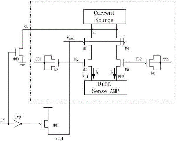
[0061] figure 2 It is a 3TP-type MTP storage unit based on a standard CMOS logic architecture. On the basis of it, a differential architecture is adopted, and an NBTI recovery circuit is added at the same time.

[0062] see figure 2 As shown, the basic module is a 3T MTP storage unit; the top module is a constant current source module Current Sourced, which is usually realized by a MOS current source operating in the saturation region, and its advantage is that it is compatible with standard processes and has a stable current; PMOS tube M1 And the PMOS transistor M4 is a selection transistor, the gate of which is connected to the gate voltage Vsel of the word line, the source is connected to the above-mentioned constant current source module Current Sourced, the drain is respectively connected to the MOS transistor M2 and the MOS transistor M5, and the substrate is directly connected to the source , usually the gate voltage Vsel is high voltage, so there are special require...


PUM


Abstract

The invention discloses a differential architecture storage unit for improving the NBTI (Negative Bias Temperature Instability) effect of a P-type NVM (Non Volatile Memory). The storage unit is composed of a P-type NVM storage unit and an NBTI recovery circuit, wherein the P-type NVM storage unit is of a floating gate type architecture or is a logic structure NVM storage unit based on a standard CMOS (Complementary Metal Oxide Semiconductor) process. By adopting a differential architecture based on the traditional P-type NVM storage unit, the matching property of bit line signals input to a differential amplifier is ensured, and the reliability and stability of the storage unit are improved; and the recovery circuit is simultaneously added to reduce the influence of the NBTI effect after the P-type NVM works under a high voltage, so that the power consumption of the circuit can be effectively reduced, and the overall stability of the memory is improved. The stability of the storage unit is obviously improved, and the storage unit has important research significance and broad market prospect.

Description

technical field [0001] The invention relates to a differential architecture NVM memory unit, in particular to a differential architecture P-type NVM memory unit added with an NBTI restoration circuit. Background technique [0002] We generally divide memory into two categories: one is volatile, that is, the memory loses the information stored in it immediately after the system is turned off, and it needs a continuous power supply to maintain data; the other is non-volatile, which Data information can still be retained when the system is turned off or in a state of no power. Most memory is non-volatile memory. [0003] A traditional non-volatile memory is a MOS transistor, which has a gate, a source and a drain. Different from other MOS transistors, his gate consists of two parts: floating gate and control gate. The floating gate is between the gate oxide layer and the pole oxide layer, and the pole oxide layer is used to isolate the floating gate. Between the control gat...

Claims


Application Information

Patent Timeline
IPC IPC(8): G11C16/04
CPCG11C16/0433
Inventor 翁宇飞李力南
Owner SUZHOU KUANWEN ELECTRONICS SCI & TECH
Why Eureka
Try Eureka