
Laminated plate theory-based optimization design method for composite bone fracture plate

A composite material, optimization design technology, applied in design optimization/simulation, calculation, electrical digital data processing, etc., can solve problems such as easy failure, poor fatigue resistance, and excessive difference between elastic modulus and bone

Inactive Publication Date: 2017-03-29
HARBIN UNIV OF SCI & TECH
View PDF3 Cites 8 Cited by
  • Summary
  • Abstract
  • Description
  • Claims
  • Application Information

AI Technical Summary

Problems solved by technology

[0003] (1) The difference between the elastic modulus and the bone is too large, and there is a stress shielding effect
[0004] (2) Its corrosion resistance and fatigue resistance are poor, and it is prone to failure
[0005] (3) Large contact area with bone, destroying the blood supply of cortical bone
[0006] (4) Cause fracture malunion, nonunion, and re-fracture after fracture, which is not conducive to fracture healing
[0007] (5) Insufficient compatibility with human tissue
[0008] (6) Does not have physical and mechanical properties compatible with natural tissue
[0010] Augat et al. found that reducing the stiffness of the fixation plate can beneficially increase the load level at the fracture site and stimulate the remodeling of callus tissue, but may also lead to an increase in factors that are not conducive to fretting of the stump (such as shear and torsion). Destabilization of fractured ends

Method used


Image

  • Laminated plate theory-based optimization design method for composite bone fracture plate
  • Laminated plate theory-based optimization design method for composite bone fracture plate
  • Laminated plate theory-based optimization design method for composite bone fracture plate

Examples


Embodiment Construction

[0104] In order to describe the present invention more specifically, the method for optimal design of the composite bone plate of the present invention will be described in detail below in conjunction with the accompanying drawings and specific embodiments.

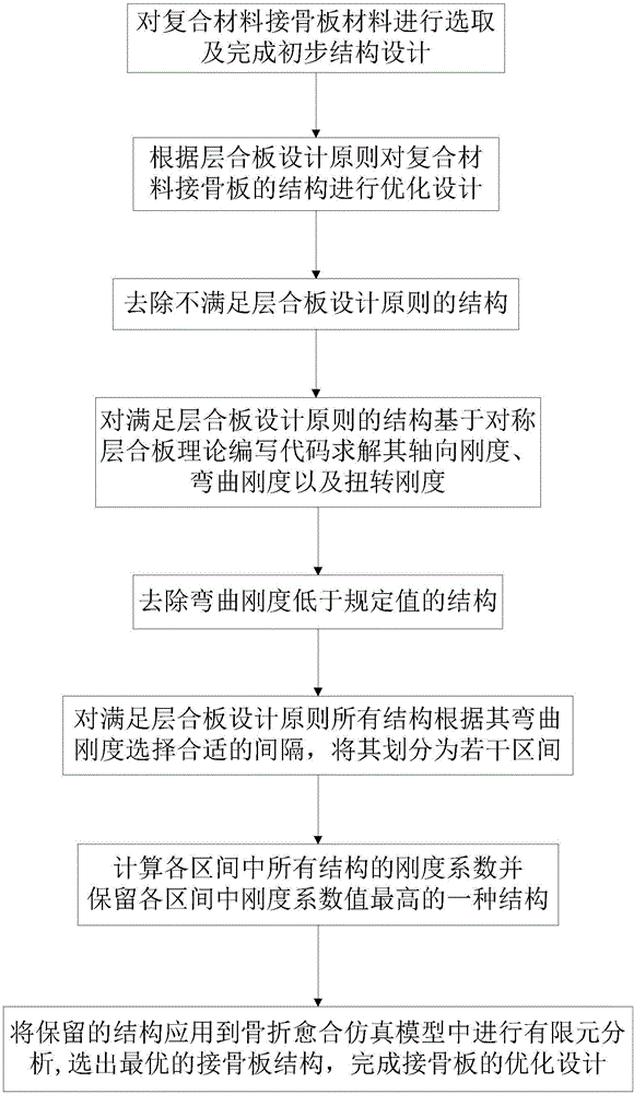
[0105] Such as figure 1 As shown, an optimal design method of composite bone plate based on laminate theory includes the following steps:

[0106] Step 1: Optimizing the structure of the composite material bone plate, the outer layer material of the composite material bone plate is carbon fiber and / or epoxy resin, and the inner layer material is flax fiber and / or epoxy resin;

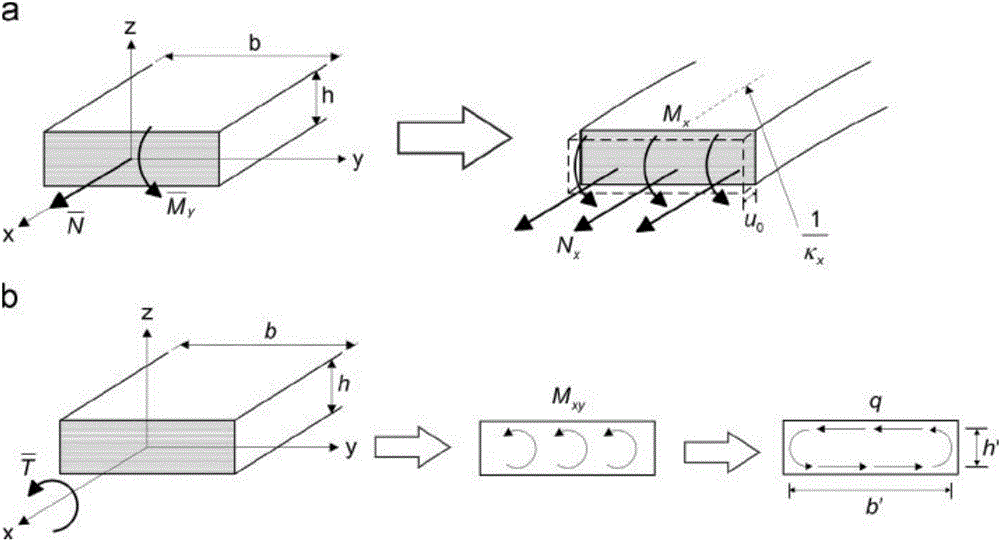
[0107] Step 2: The structural essence of the composite material bone plate is a laminated plate structure. The optimized design first reasonably designs the total thickness of the bone plate according to the actual fracture site of the human body, and then calculates the total number of layers of the laminated plate, carbon fiber and The quantity ...


PUM


Abstract

The invention discloses a laminated plate theory-based optimization design method for a composite bone fracture plate. The method specifically comprises the steps of selecting a material of the composite bone fracture plate, performing preliminary structure design on the material, and performing optimization design on a laying layer number, a laying sequence, a laying layer direction and the like of a laminated plate; solving axial rigidity, bending rigidity and torsional rigidity based on writing codes of a symmetric laminated plate theory for a structure meeting the condition; reasonably selecting a bending rigidity value, dividing the structure into a plurality of intervals, and calculating rigidity coefficient values; reserving a plurality of structures with maximum rigidity coefficients and applying the structures to a fracture healing simulation model for performing finite element analysis; and selecting out an optimal design scheme. According to the method, the composite bone fracture plate is subjected to comprehensive optimization design, and a stress shielding phenomenon during fracture fixation is skillfully utilized, so that the axial rigidity is reduced, the bending and torsional rigidity of the bone fracture plate is maximized, and the negative influence of stress shielding on fracture healing is reduced.

Description

technical field [0001] The invention belongs to the technical field of optimization of composite material fixers, and in particular relates to a composite material bone plate optimization design method based on laminated plate theory. Background technique [0002] Internal fixation with bone plate is one of the common methods in orthopedic treatment of fractures. After plate fixation of the fracture site, the degree of mobility of the fracture site depends on the magnitude of the external load, the stiffness of the fixation system, and the stiffness of the bridging tissues between the fractures. Traditional bone plates are mostly made of metal materials, which have the following disadvantages: [0003] (1) The difference between the elastic modulus and the bone is too large, and there is a stress shielding effect. [0004] (2) It has poor corrosion resistance and fatigue resistance, and is prone to failure. [0005] (3) The contact area with the bone is large and the bloo...

Claims


Application Information

Patent Timeline
IPC IPC(8): G06F17/50
CPCG06F30/23
Inventor 王沫楠王新宇杨宁
Owner HARBIN UNIV OF SCI & TECH
Learn More