Film magnetic characterization instrument under vacuum

A vacuum environment and instrument technology, applied in the field of thin-film magnetic characterization instruments, can solve the problems of inability to obtain large-area data of samples in a relatively short time, no good solution for shock absorption, and inability to ensure the constant temperature of samples, and reduce the optical path. Adjusting difficulty, reducing the difficulty of optical path adjustment, and improving the effect of test efficiency

Inactive Publication Date: 2017-04-05
BEIHANG UNIV
View PDF8 Cites 9 Cited by
  • Summary
  • Abstract
  • Description
  • Claims
  • Application Information

AI Technical Summary

Problems solved by technology

[0004] It is difficult to adjust the optical path of the existing public technical solutions, and it is impossible to perform magnetic characterization during the thin film preparation process. At the same time, because the sample cannot be guaranteed to be in a constant temperature state during the test process, it is not suitable to use a laser with a high repetition rate (MHz level) as the pump laser. source
Therefore, the measurement efficiency of the existing test system is low, and it is impossible to obtain large-area data of the sample in a short period of time
In particular, the test environment exposed to air cannot protect samples whose surface materials are easily oxidized. If the measurement system is equipped with a vacuum chamber, there is no good solution for shock absorption.

Method used


Image

  • Film magnetic characterization instrument under vacuum
  • Film magnetic characterization instrument under vacuum
  • Film magnetic characterization instrument under vacuum

Examples


Embodiment Construction

[0063] The specific embodiments of the present invention will be described in further detail below in conjunction with the accompanying drawings.

[0064] Before introducing the co-operation principle of a thin film magnetic characterization system in a vacuum environment of the present invention, it is stipulated that the amplitude of the Kerr signal after noise reduction is proportional to the magnitude of the magnetization of the sample.

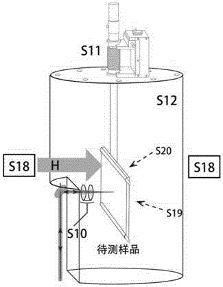
[0065] Such as image 3 Shown, in this embodiment, a kind of thin film magnetic characterization instrument under vacuum environment, it mainly comprises:

[0066] Ultrafast laser S1, used to generate laser light, is located at the input end of the entire magnetic characterization instrument;

[0067] Three semi-reflective half-lenses S2 are used for laser beam splitting and rendezvous, among which the first half-reflective half-mirror is located at the back end of the ultrafast laser S1, and the other two are located at the front end of...


PUM


Abstract

The invention discloses a film magnetic characterization instrument under vacuum. The instrument includes an ultra-fast laser, beam splitters, a time delay line, reflectors, a polarization splitting prism, a frequency multiplier, two optical filters, at least one rectangular prism, an optical chopper, an optical focusing lens group, a multi-fiber sample rack, a hermetic vacuum cavity, a 1/2 slide, a beam splitter prism, a photodiode, a phase-locked amplifier, a magnet, a constant temperature apparatus, a translation stage, and an imaging apparatus. According to the invention, the instrument, by implementing in situ characterization in the preparation of films, increases measuring efficiency and precision. The instrument can achieve imaging effects by preparing a multi-fiber sample adjusting apparatus with as high as five fibers in combination with the translation stage for samples. Co-axial and vertical incidence of pump and detection beams simplifies light paths and reduces the difficulty in adjusting light paths. In addition, the instrument can enable samples to conduct magnetic characterization inside the vacuum cavity and prevents air or water vapor from polluting the samples.

Description

technical field [0001] The invention relates to a thin-film magnetic characterization instrument in a vacuum environment, in particular to an instrument construction scheme for realizing thin-film magnetic characterization in a vacuum environment based on the magneto-optical Kerr effect, and belongs to the technical fields of condensed matter physics and information storage. Background technique [0002] In recent years, magnetic storage devices based on spintronics have opened up a new information age of big data, cloud computing and high-speed search engines. As an emerging interdisciplinary subject of condensed matter physics, microelectronics and material science, spintronics uses the spin properties of electrons to design electronic devices, and the interface between ferromagnetic materials and other materials is one of the important research directions in this field. At the same time, in the magnetic ultra-thin multilayer film system, the magnetic properties of each la...

Claims


Application Information

Patent Timeline
Patent Type & Authority Applications(China)
IPC IPC(8): G01R33/12
CPCG01R33/12
Inventor 赵巍胜曹安妮林晓阳雷娜赵晓璇张博宇
Owner BEIHANG UNIV
Why Eureka
Try Eureka