Adaptive biasing radio frequency power amplifier

A technology of adaptive bias and RF power, applied in the direction of power amplifiers, RF amplifiers, amplifiers, etc., to achieve the effects of reducing on-resistance and on-voltage drop, reducing phase distortion, and increasing output power

Active Publication Date: 2017-04-19
RDA MICROELECTRONICS SHANGHAICO LTD
View PDF6 Cites 23 Cited by
  • Summary
  • Abstract
  • Description
  • Claims
  • Application Information

AI Technical Summary

Problems solved by technology

The bias circuit is mainly composed of resistors and...

Method used


Image

  • Adaptive biasing radio frequency power amplifier
  • Adaptive biasing radio frequency power amplifier
  • Adaptive biasing radio frequency power amplifier

Examples


Embodiment Construction

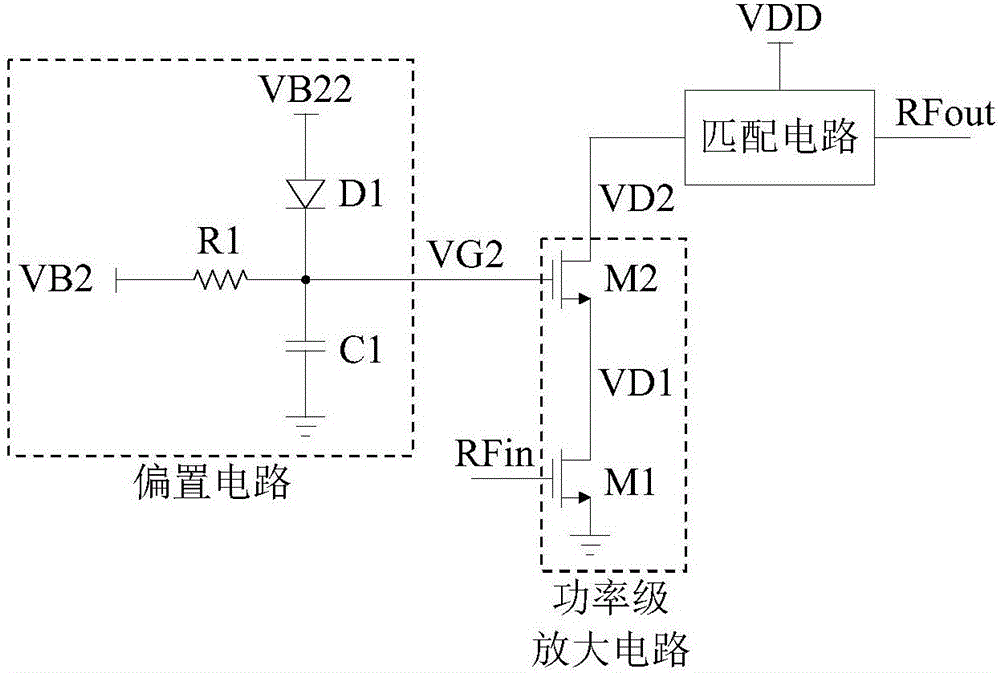
[0030] see image 3 , which is Embodiment 1 of the radio frequency power amplifier provided in this application. The radio frequency power amplifier includes a bias circuit and a power stage amplifying circuit. For clarity, image 3 The matching circuit is also schematically shown in .

[0031] The bias circuit includes a resistor R1, a diode D1 and a capacitor C1, which are used to provide a dynamic bias voltage for the transistor M2 in the power stage amplifier circuit. The working voltage VB2 is connected to one end of the resistor R1, and the other end of the resistor R1 serves as the output terminal of the bias circuit to provide a dynamic bias voltage for the transistor M2. The dynamic bias voltage includes a static working voltage VB2 and a dynamic voltage generated by a dynamic current passing through the resistor R1, and the dynamic current refers to a DC component of the current flowing through the resistor R1. The gate voltage VG2 of the transistor 2 M2 is the c...


PUM


Abstract

The application discloses an adaptive biasing radio frequency power amplifier comprising a biasing circuit and a power level amplifying circuit. The biasing circuit is used for providing dynamic bias voltage for a transistor II in the power level amplifying circuit; the work voltage I is connected to one end of a resistor I; the other end of the resistor I is used as an output end of the biasing circuit; the work voltage II is connected to the anode of a diode I; the cathode of the diode I is connected to the output end of the biasing circuit; the value of the work voltage II makes the diode I in a default critical conduction status. the power level amplifying circuit comprises a transistor I and the transistor II, which adopt common source and common gate structures; the transistor I adopts common source connection and the grid of the transistor I receives radio frequency input signals; the transistor II adopts common grade connection and the drain electrode of the transistor II outputs drain voltage II. The application provides adaptive biasing voltage postponing gain compression and reducing phase distortion caused by non-linear capacity.

Description

technical field [0001] This application relates to a radio frequency power amplifier. Background technique [0002] RF power amplifier (RF power amplifier) ​​is an electronic amplifier used to convert lower power radio frequency signals to higher power. A typical application of a radio frequency power amplifier is to drive an antenna in a transmitter (transmitter), that is, to amplify a modulated radio frequency signal to a required power value and send it to the antenna for transmission. The design specifications of RF power amplifiers usually include gain, output power, bandwidth, efficiency, linearity, input and output impedance matching, heat generation, etc. [0003] The efficiency of an RF power amplifier refers to its ability to convert the DC power of the power supply into the output power of the RF signal. The power supply that is not converted into the output power of the RF signal becomes heat and dissipates, so the low-efficiency RF power amplifier has a high h...

Claims


Application Information

Patent Timeline
IPC IPC(8): H03F1/30H03F3/193H03F3/21H03F3/24
CPCH03F1/30H03F3/193H03F3/21H03F3/245H03F2200/451
Inventor 孙亚楠江亮张海兵贾斌
Owner RDA MICROELECTRONICS SHANGHAICO LTD
Why Eureka
Try Eureka