An automatic installation system for railway t-beam steel formwork

An automatic installation and steel formwork technology, which is applied to fluid pressure actuation system components, fluid pressure actuation devices, molds, etc., can solve the problems of gantry cranes that cannot be synchronized, poor control accuracy, and low operating safety factor, so as to improve mobile work. Efficiency, improvement of construction safety, and high degree of automation

Active Publication Date: 2019-01-25
韩秦安
View PDF5 Cites 0 Cited by
  • Summary
  • Abstract
  • Description
  • Claims
  • Application Information

AI Technical Summary

Problems solved by technology

[0002] During the construction of prefabricated beam steel formwork, part of the beam field is controlled by hydraulic system, but the control method is simple, the control accuracy is poor, and its operation safety factor is low
This method of controlling mold clamping and demoulding is a pre-setting mode. When specific mold clamping and demoulding are required, matching displacement control and pressure control cannot be provided, which may easily cause excessive beam size error and system pressure. Excessively high damage to the formwork
[0003] At the same time, the disassembly and installation of the steel formwork requires the assistance of gantry cranes or other hoisting equipment, and the gantry cranes cannot be synchronized when the steel formwork is moving. On the one hand, this phenomenon makes the hoisting operation on the construction site unsafe. Under the operation, the deformation is relatively large, which will also increase the construction period to a certain extent

Method used


Image

  • An automatic installation system for railway t-beam steel formwork
  • An automatic installation system for railway t-beam steel formwork
  • An automatic installation system for railway t-beam steel formwork

Examples


Embodiment 1

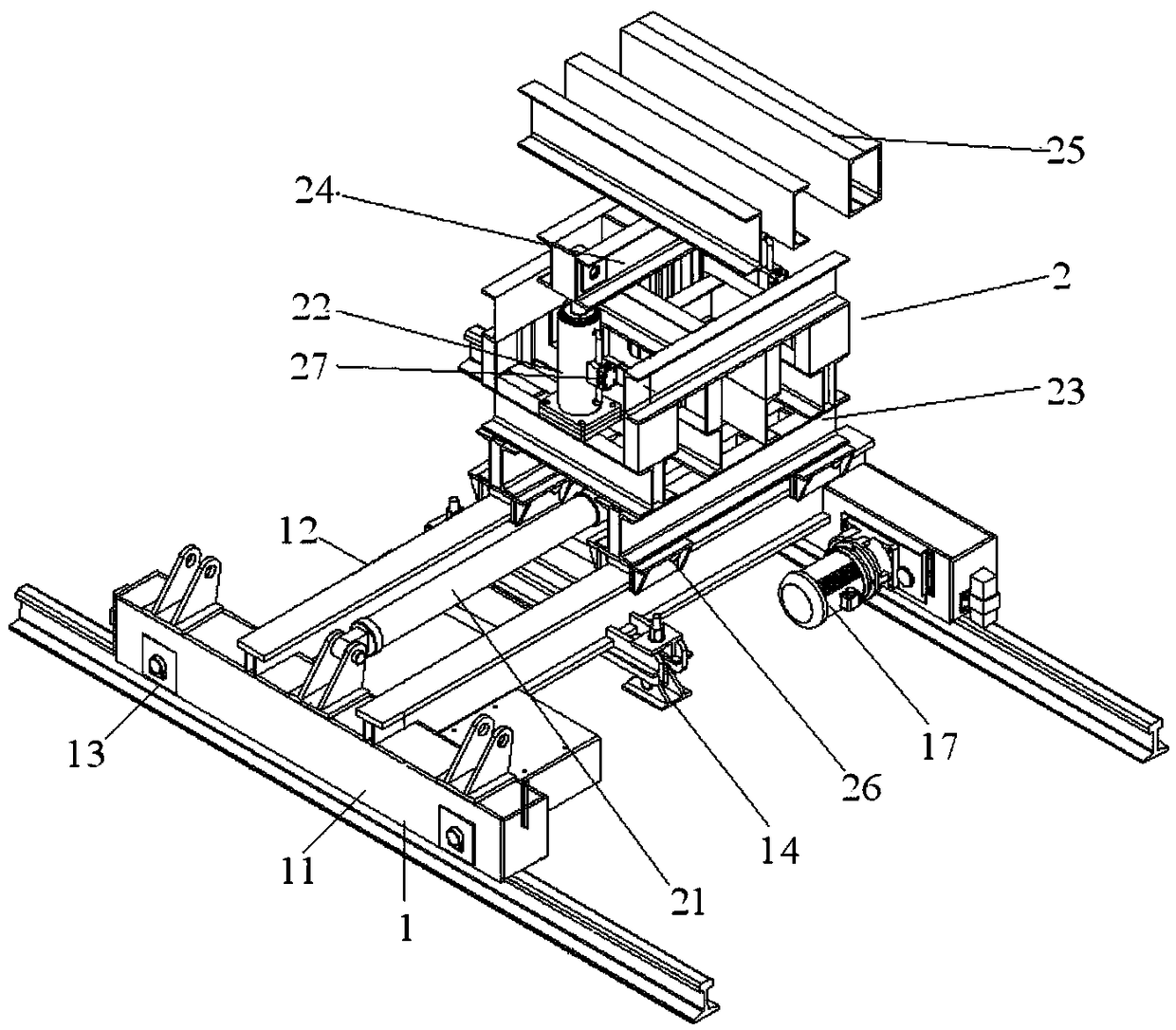
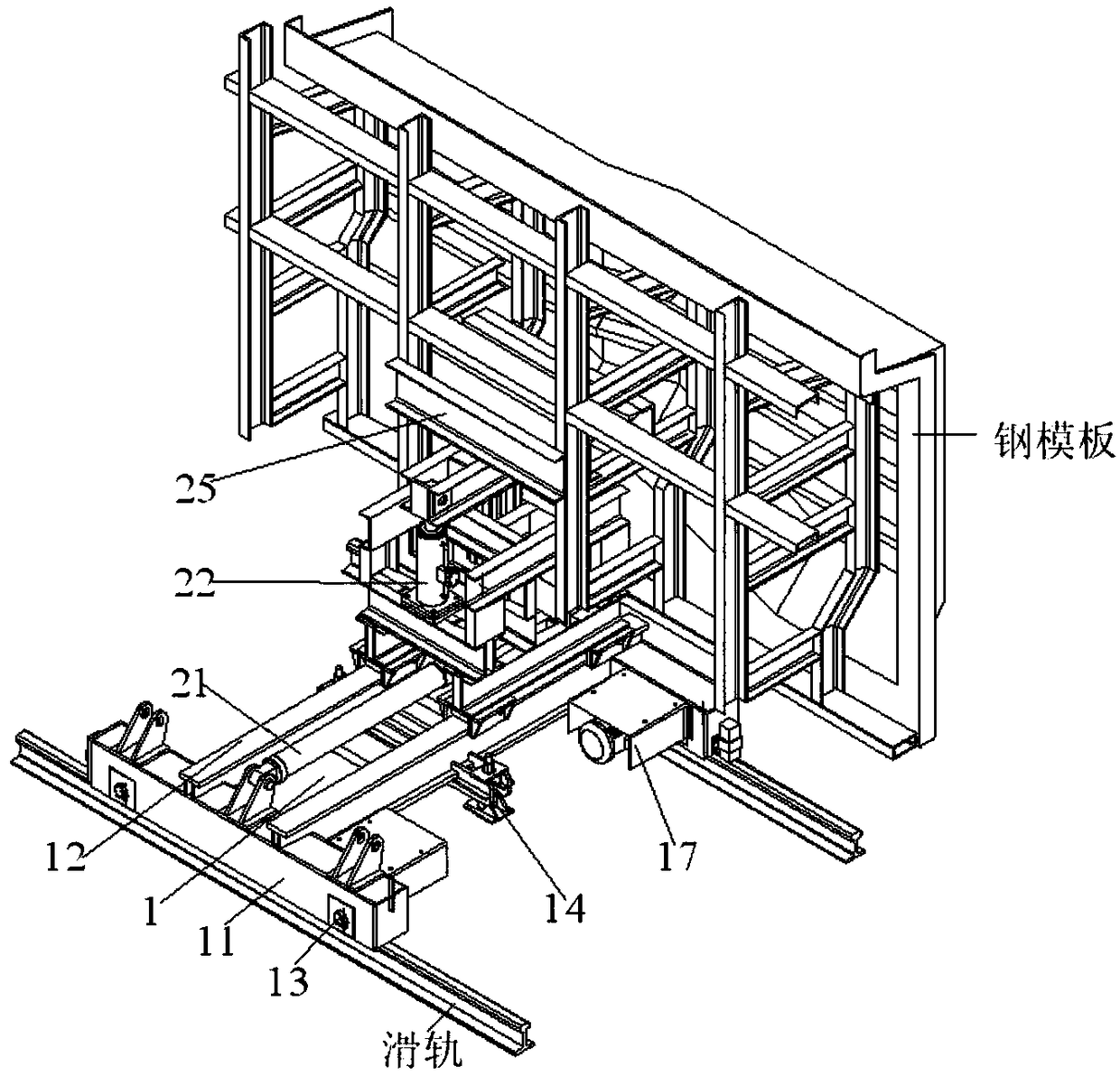
[0044] Comply with the above technical solutions, such as Figure 2 to Figure 13 As shown, this embodiment provides an automatic installation system for railway T-beam steel formwork, including trolley walking equipment 1, automatic lifting equipment 2 and hydraulic station system 3;

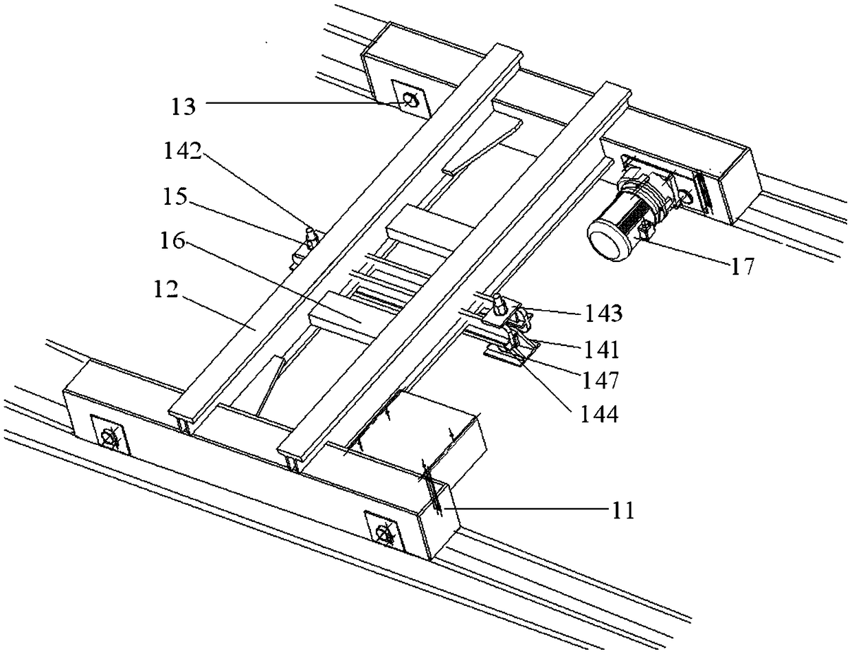
[0045] The trolley walking equipment 1 includes cross beams 11 parallel to each other. Longitudinal beams 12 parallel to each other are connected between the cross beams 11. Walking wheels 13 are arranged on the bottom of the cross beams 11. An anti-dumping mechanism 14 is installed on the longitudinal beams 12. The anti-dumping mechanism includes ear seats 141, movable trunnion 142, fastening plate 143 and support plate 144, the center of fastening plate 143 is processed with through hole 145, the lower surface of fastening plate 143 is provided with two parallel vertical plates 146, ear seat 141 and movable One end of the trunnion 142 is connected by a bolt 147, and the other end of the movabl...

Embodiment 2

[0062] The railway T-beam steel formwork automatic installation system of the present invention has been used in the actual construction of railway prefabricated beams and has achieved good results, as follows:

[0063] (1) Calculation of economic benefits before and after using the automatic installation system of railway T-beam steel formwork of the present invention, according to conventional construction, most parts of the system need to be hoisted and manually transported, using the present invention to realize overall movement, faster speed, and significantly reduced labor intensity , adopting the system of the present invention greatly reduces the cost expenditure and obtains better social and economic benefits.

[0064] The comparison is made from the three aspects of required team members, mold removal and installation time, and benefit analysis. The results are as follows:

[0065]

[0066]

[0067] (2) use the comparison of prefabricated T beam quality inspect...


PUM


Abstract

The invention discloses a railway T-shaped beam steel template automatic mounting system which comprises trolley walking equipment, automatic lifting equipment and a hydraulic station system; the trolley walking equipment is composed of mutually parallel cross beams; mutually parallel longitudinal beams are connected between the cross beams and are provided with a dumping prevention mechanism; the automatic lifting equipment is composed of a horizontal oil cylinder, a vertical oil cylinder, a lower supporting frame and an upper supporting frame; the hydraulic station system is composed of an oil tank protective cover, an oil tank, a safety valve arranged on the oil tank, electromagnetic directional valves, proportional servo valves, valve blocks, an oil pump motor group, a liquid level relay, an oil return filter and a control handle. According to the railway T-shaped beam steel template automatic mounting system, position control of a steel template in the horizontal direction and the vertical direction can be realized simultaneously; in the mold closing and demolding process, the steel template is accurately positioned; meanwhile, the working pressure of the oil cylinder can be timely detected through a pressure sensor, damage of the steel template caused by overlarge pressure is prevented, and the construction safety is also improved.

Description

technical field [0001] The invention relates to the technical field of railway construction automation equipment, in particular to an automatic installation system for railway T-beam steel formwork. Background technique [0002] During the construction of prefabricated beam steel formwork, part of the beam field is controlled by hydraulic system, but the control method is simple, the control accuracy is poor, and its operation safety factor is low. This method of controlling mold clamping and demoulding is a pre-setting mode. When specific mold clamping and demoulding are required, matching displacement control and pressure control cannot be provided, which may easily cause excessive beam size error and system pressure. Too high will cause damage to the formwork. [0003] At the same time, the disassembly and installation of the steel formwork requires the assistance of gantry cranes or other hoisting equipment, and the gantry cranes cannot be synchronized when the steel fo...

Claims


Application Information

Patent Timeline
Patent Type & Authority Patents(China)
IPC IPC(8): B28B7/00F15B11/16F15B21/041
CPCB28B7/0002B28B7/0041F15B11/16F15B21/041
Inventor 洪刚院韩秦宝
Owner 韩秦安
Why Eureka
Try Eureka