Eureka AIR delivers breakthrough ideas for toughest innovation challenges, trusted by R&D personnel around the world.

Pneumatic fluidized coating device and lithium ion battery cathode material coating process

A lithium-ion battery and coating device technology, which is applied to battery electrodes, secondary batteries, circuits, etc., can solve problems such as the difficulty in ensuring the integrity of asphalt powder coating, the quality of the production process is not easy to control, and the operation of high-temperature reactors is troublesome. , to achieve the effect suitable for large-scale industrial production, simple structure and good coating effect

Active Publication Date: 2017-04-26
WEIFANG ZHENGYUAN POWDER ENG EQUIP
View PDF7 Cites 4 Cited by
  • Summary
  • Abstract
  • Description
  • Claims
  • Application Information

AI Technical Summary

Problems solved by technology

However, there are defects in the existing three coating methods
The production method of solid-phase mixing is simple, but the quality of the production process is not easy to control, especially the integrity of asphalt micropowder coating is difficult to guarantee; the conditions of vapor phase deposition are relatively harsh, the cost is high, and it is not yet industrialized; liquid phase mixing package When coating, the asphalt is dissolved in an organic solvent, and then mixed, after a high temperature treatment at 400-500 ° C, the solvent is evaporated to form a mesophase pitch, the graphite is coated, the light pitch and solvent are removed, and then carbonized. Coated carbon is formed on the surface of carbon particles. The negative electrode material obtained by this method has good cycle performance, but the process of this method is complicated, the operation of the high-temperature reactor is cumbersome, the production cost is high, and it causes great pollution to the environment.

Method used


Image

  • Pneumatic fluidized coating device and lithium ion battery cathode material coating process

Examples


Embodiment Construction

[0033] In order to make the object, technical solution and advantages of the present invention clearer, the present invention will be further described in detail below in conjunction with the accompanying drawings and embodiments. It should be understood that the specific embodiments described here are only used to explain the present invention, not to limit the present invention.

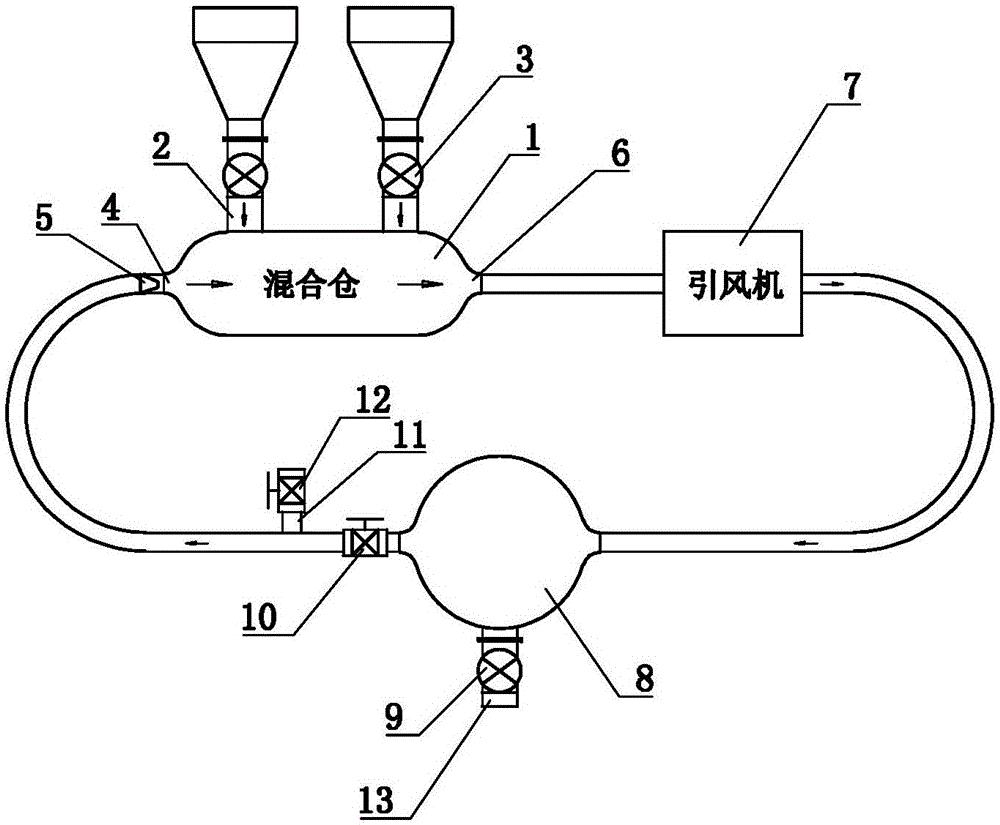
[0034] refer to figure 1 , The pneumatic fluidized coating device of the present invention includes a mixing chamber 1, and the mixing chamber 1 is provided with two material inlets, and the feed pipes 2 connected to the two material inlets are respectively provided with feed valves 3 .

[0035] An airflow inlet 4 and an airflow outlet 6 are respectively arranged on the mixing chamber 1 , and the airflow inlet 4 and the airflow outlet 6 are respectively arranged at both ends of the mixing chamber 1 . An induced fan 7 is arranged between the air outlet 6 and the air inlet 4, the air outlet 4 is con...


PUM


Abstract

The invention discloses a pneumatic fluidized coating device, which comprises a mixing bin, wherein two material inlets are arranged in the mixing bin and feed valves are both arranged on feed pipelines respectively connected to the two feed inlets; an airflow inlet and an airflow outlet are respectively arranged in the mixing bin, an induced draft fan is arranged between the airflow inlet and the airflow outlet, the airflow outlet is connected to an inlet of the induced draft fan through a pipeline, and the airflow inlet is connected to an outlet of the induced draft fan through a pipeline; the pipeline between the outlet of the induced draft fan and the airflow inlet is connected to a discharge pipe, and a discharge valve is arranged on the discharge pipe; and a control valve is arranged on a pipeline between the discharge pipe and the airflow inlet, a pipeline between the control valve and the airflow inlet is connected to a bypass line, and a bypass valve is arranged on the bypass line. The invention also discloses a lithium ion battery cathode material coating process. The pneumatic fluidized coating device and the lithium ion battery cathode material coating process have good coating effect and cannot pollute the environment.

Description

technical field [0001] The invention relates to the field of lithium-ion battery negative electrode materials, in particular to a pneumatic fluidization coating device and a lithium-ion battery negative electrode material coating process. Background technique [0002] The negative electrode materials of lithium-ion batteries include graphite, carbon and metal oxides, etc., and graphite is currently the most commonly used negative electrode material for lithium-ion batteries. During the charging process of lithium-ion batteries, it can react with Li+ to form LiC6 compounds. The theoretical ratio The capacity is 372mAh / g. At present, the actual specific capacity of the graphite anode material with the highest capacity is 360mAh / g, which is close to the theoretical capacity. However, most graphite anode materials have a specific capacity of 300mAh / g, which is relatively low. [0003] In order to overcome the shortcomings of graphite materials such as low specific capacity, low ...

Claims


Application Information

Patent Timeline
Patent Type & Authority Applications(China)
IPC IPC(8): H01M4/36H01M4/583H01M4/48H01M4/62H01M10/0525
CPCH01M4/362H01M4/483H01M4/583H01M4/62H01M10/0525Y02E60/10
Inventor 王卫林
Owner WEIFANG ZHENGYUAN POWDER ENG EQUIP
Why Eureka
Eureka Blog
Learn More