A kind of surface treatment device and surface treatment method of diamond wire cutting silicon wafer
A diamond wire and surface treatment technology, which is applied in metal processing equipment, machine tools suitable for grinding workpiece planes, grinding workpiece supports, etc., can solve problems such as periodic cutting scratches, and achieve surface treatment efficiency improvement, high efficiency and stability The effect of fixing and saving processing costs
- Summary
- Abstract
- Description
- Claims
- Application Information
AI Technical Summary
Problems solved by technology
Method used
Image
Examples
Embodiment 1
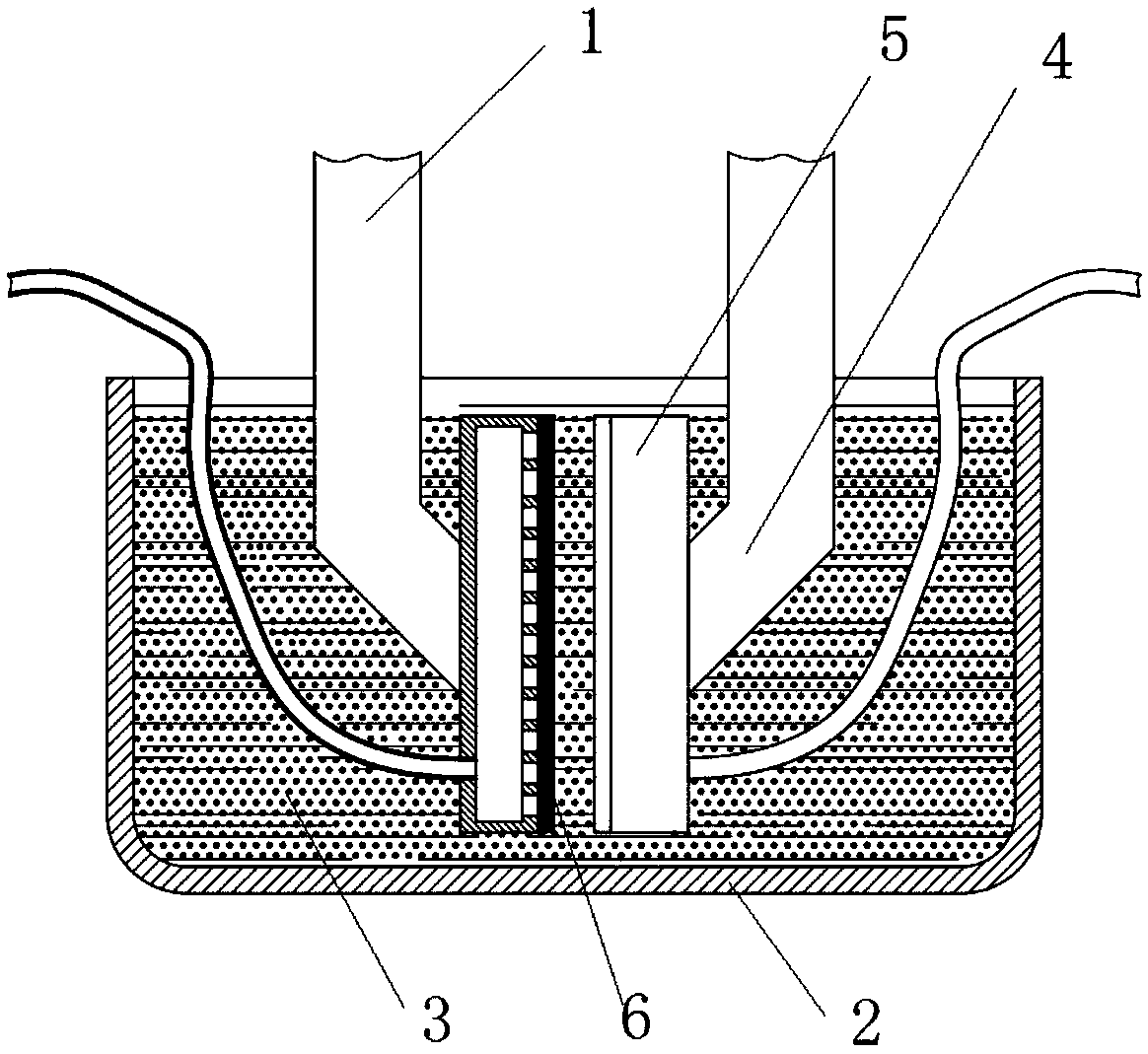
[0048] see figure 1, the present embodiment is a surface treatment device for diamond wire-cut silicon wafers, the structure of which includes two oppositely disposed abrasive racks 1 and an abrasive tank 2 with an open top, and the abrasive tank 2 is filled with abrasive particle suspension 3 . The abrasive frame 1 includes a motion control arm 4 and an adsorption device 5 fixed at one end of the motion control arm 4 , the adsorption device 5 is used to adsorb and fix a diamond wire-cut silicon wafer 6 to be processed.
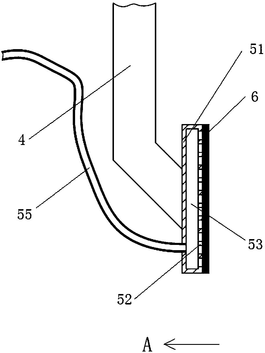
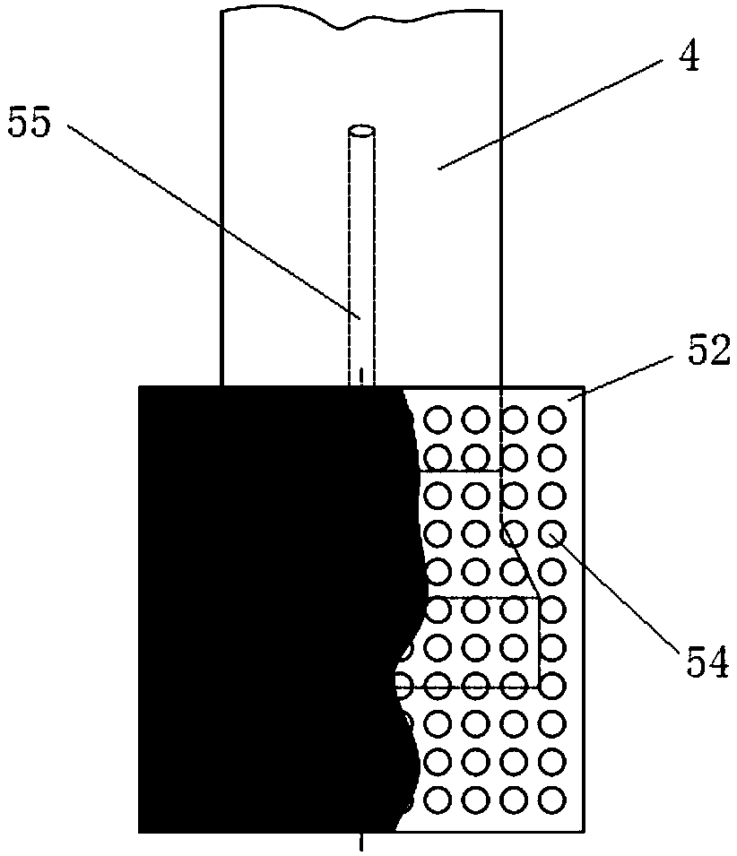
[0049] see figure 2 In this embodiment, the more preferred structure of the adsorption device 5 includes an adsorption disc 51 and an abrasive disc 52 connected as one, an adsorption cavity 53 is formed between the adsorption disc 51 and the abrasive disc 52, and one end of the adsorption disc 51 and the motion control arm 4 Fixed connection. Such as image 3 As shown, the surface of the abrasive disk 52 is provided with a plurality of adsorption holes 54...
Embodiment 2
[0051] see Figure 4 , the present embodiment is another surface treatment device for diamond wire-cut silicon wafers. Its structure includes two oppositely arranged first abrasive racks 11, second abrasive racks 12 and an abrasive tank 2 with an open top. Filled with abrasive particle suspension 3. The first abrasive frame 11 includes a motion control arm 4 and an adsorption device 5 fixed at one end of the motion control arm 4 , the adsorption device 5 is used to adsorb and fix the diamond wire-cut silicon wafer 6 to be processed. An abrasive device 7 is installed on the second abrasive frame 12 . Such as Figure 5 As shown, the abrasive device 7 in this embodiment is provided with a flat abrasive surface 71 ( Figure 5 for Figure 4 B-direction view of the medium abrasive device). In actual use, the abrasive device 7 can be fixed in the abrasive tank 2, and the diamond wire-cut silicon wafer 6 to be processed is closely attached to the abrasive surface 71, and an abras...
Embodiment 3
[0053] see Image 6 ( Image 6 for Figure 4 The B-direction view of the abrasive device in the middle), the difference between this embodiment and the second embodiment is that the abrasive device 7 has an abrasive surface 72 in the shape of a round roller. During the abrasive treatment, the abrasive surface 72 can rotate around its axis on the surface to be abrasive of the diamond wire-cut silicon wafer 6 .
PUM
| Property | Measurement | Unit |
|---|---|---|
| particle diameter | aaaaa | aaaaa |
| particle diameter | aaaaa | aaaaa |
| particle diameter | aaaaa | aaaaa |
Abstract
Description
Claims
Application Information
 - R&D
- Intellectual Property
- Life Sciences
- Materials
- Tech Scout
- Unparalleled Data Quality
- Higher Quality Content
- 60% Fewer Hallucinations
Browse by: Latest US Patents, China's latest patents, Technical Efficacy Thesaurus, Application Domain, Technology Topic, Popular Technical Reports.
© 2025 PatSnap. All rights reserved.Legal|Privacy policy|Modern Slavery Act Transparency Statement|Sitemap|About US| Contact US: help@patsnap.com


