
Efficient sewage treatment method based on MBR (Membrane Bioreactor) membrane

A sewage treatment method and technology of sewage treatment system, applied in biological water/sewage treatment, water/sewage multi-stage treatment, water/sludge/sewage treatment, etc., can solve the problem of low purification efficiency of MBR membrane filtration and high cost of sewage treatment , poor aeration effect, etc., to achieve the effect of improving equipment utilization, improving aeration effect, and simple structure

Active Publication Date: 2017-05-10
浙江秀水环保有限公司
View PDF6 Cites 3 Cited by
  • Summary
  • Abstract
  • Description
  • Claims
  • Application Information

AI Technical Summary

Problems solved by technology

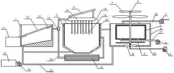
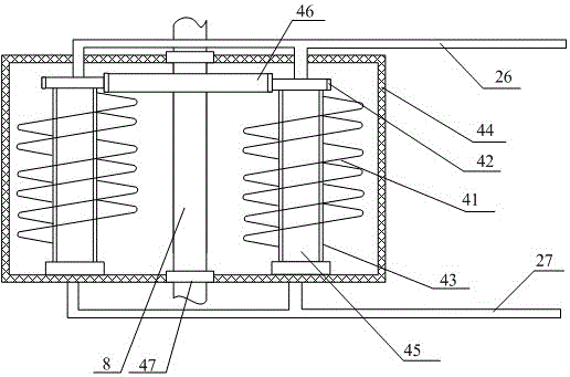
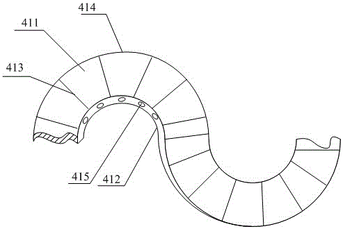
[0007] 1. In order to solve the above-mentioned technical problems, the present invention provides a sewage treatment method based on an MBR membrane-based high-efficiency sewage treatment system to solve the problem of low filtration and purification efficiency of MBR membranes in existing sewage treatment systems, low utilization value, and aeration Poor effect, low utilization rate of equipment, complex structure, large floor area, high energy consumption, high cost of sewage treatment, a high-efficiency sewage treatment system based on MBR membrane, including regulating pool, facultative pool, MBR pool, MBR membrane module, outlet pump, MBR membrane cleaning pump, wind impeller, wind drive rod, aeration wheel, blower, filter residue tank, grid plate, vibrator, three-way solenoid valve, underground cooling pipe, heating tank, photovoltaic panel, Supporting air bag, temperature sensor, heat absorbing layer, fixed seat, sewage pump, sludge tank, drainage pipe, sewage pipe, drain pipe, cleaning pipe and air pipe, the regulating pool is connected with the facultative pool through a three-way solenoid valve; The MBR membrane module is installed inside the MBR pool; the outlet pump is connected to the upper part of the MBR membrane module through a drain pipe; the MBR membrane cleaning pump is connected to the lower part of the MBR membrane module through a cleaning pipe; the wind impeller Installed on the top of the wind driving rod; the aeration wheel is installed on the lower part of the wind driving rod; the wind driving rod is installed on the upper part of the fixed seat; the blower is connected with the aeration wheel through the air pipe; The filter residue pool is installed on the outer side of the grid plate; the vibrator is installed under the grid plate; the underground cooling pipe is connected with the aerobic pool through the drainage pipe; the heating water tank is installed under the photovoltaic panel; the The above-mentioned heating water tank is fixed on the top of the aerobic pool through the supporting air bag; the described temperature sensor is installed in the inside of the aerobic pool; the heat-absorbing layer is adhered to the inside of the MBR pool; It is connected with the sludge tank; the sewage pipe is connected with the aerobic tank or the MBR tank; the MBR membrane module includes the MBR membrane body, the driven gear, the support pipe, the filter screen, the water outlet chamber, the driving gear and the bearing, and the The MBR membrane body is installed around the outside of the support tube; the driven gear is fixed on the upper part of the support tube; the driven gear is meshed with the driving gear; the driving gear is fixed on the middle of the wind drive rod The filter screen is installed on the outside of the MBR membrane module; the water outlet cavity is arranged inside the support tube; the support tube is connected to the filter screen through a bearing; the MBR membrane body includes an upper film layer, and the lower film layer, lining strips, reinforcing frame and water outlet, lining strips are installed between the upper film layer and the lower film layer; the reinforcing frame is installed on the inner side of the upper film layer and the lower film layer; the water outlet hole It is arranged on the side wall of the support pipe; the water outlet hole communicates with the water outlet chamber, and the aeration wheel includes an aeration plate, an aeration hole, a connecting pipe and a fixed sleeve, and the side of the aeration plate is provided with an aeration The aeration hole is connected to the connecting pipe; the connecting pipe is connected to the wind driving rod through the fixed sleeve; the connecting pipe is connected to the blower through the air pipe; the steps of the method are as follows: firstly, the sewage is passed through the grid in the regulating tank. The sludge is deposited behind the grid and enters the aerobic tank through the three-way solenoid valve. When the temperature of the sewage in the aerobic tank is high, the sewage in the regulating tank flows into the aerobic tank through the underground cooling pipe. When the temperature of the sewage in the aerobic tank is high When it is low, by controlling the three-way solenoid valve, the sewage in the regulating tank flows into the aerobic tank through the heating tank; the wind driving rod is driven by the wind impeller to rotate, the driving gear drives two driven gears, and the driven gear drives two MBRs The membrane body rotates, and the sewage forms a pressure difference between the upper membrane layer and the lower membrane layer, which improves the filtration efficiency and is discharged through the drain pipe after purification; at the same time, the aeration wheel rotates continuously with the wind drive rod to expand the aeration area, improving equipment utilization

Method used


Image

  • Efficient sewage treatment method based on MBR (Membrane Bioreactor) membrane
  • Efficient sewage treatment method based on MBR (Membrane Bioreactor) membrane
  • Efficient sewage treatment method based on MBR (Membrane Bioreactor) membrane

Examples


Embodiment Construction

[0028]The present invention will be further described below in conjunction with accompanying drawing:

[0029] as attached figure 1 to attach Figure 5 shown

[0030] The invention provides a sewage treatment method based on an MBR membrane-based high-efficiency sewage treatment system. The treatment system includes a regulating tank 1, an aerobic tank 2, an MBR tank 3, an MBR membrane module 4, an MBR membrane body 41, a driven gear 42, a support Pipe 43, filter screen 44, water outlet cavity 45, drive gear 46 and bearing 47 upper film layer 411, lower film layer 412, liner 413, reinforcement frame 414 and water outlet hole 415 water outlet pump 5, MBR membrane cleaning pump 6, wind impeller 7. Wind drive rod 8, aeration wheel 9, blower 10, filter residue tank 11, grid plate 12, vibrator 13, three-way solenoid valve 14, underground cooling pipe 15, heating water tank 16, photovoltaic panel 17, support airbag 18 , a temperature sensor 19, a heat absorbing layer 20, a fixed ...


PUM


Abstract

The invention discloses an efficient sewage treatment method based on an MBR (Membrane Bioreactor) membrane. The method comprises the following steps: carrying out sludge precipitation after sewage passes through a grid plate (12) in an adjusting tank (1); enabling the sewage to enter a facultative tank (2) through a three-way solenoid valve (14); when the temperature of the sewage in the facultative tank (2) is relatively high, enabling the sewage in the adjusting tank (1) to flow into the facultative tank (2) through an underground cooling pipe (15); when the temperature of the sewage in the facultative tank (2) is relatively low, controlling the three-way solenoid valve (14) to enable the sewage in the adjusting tank (1) to pass through a heating water tank (16) and flow into the facultative tank (2); driving a wind power driving rod (8) by a wind power impeller (7) to rotate, and driving two driven gears (42) through a driving gear (46); driving two MBR membrane bodies by the driven gears (42) to rotate and move; forming pressure difference by the sewage between an upper membrane layer (411) and a lower membrane layer (412), so as to improve the filtering efficiency; after purifying, discharging the sewage through a water drainage pipe (26); meanwhile, driving an aeration wheel (9) to rotate incessantly along with the wind power driving rod (8), so as to enlarge the aeration area and improve the utilization rate of equipment.

Description

technical field [0001] The invention belongs to the technical field of sewage treatment, and in particular relates to a sewage treatment method of an efficient sewage treatment system based on an MBR membrane. Background technique [0002] With the improvement of centralized batch processing efficiency of large urban sewage plants and industrial wastewater treatment plants, a large number of scattered and miniaturized sewage discharges such as the vast number of small and medium-sized towns, rural areas, ships, and tourist attractions have become important sources of water pollution in my country. Due to its unique sewage discharge and distribution characteristics, it has become an urgent need to develop and promote a small, integrated and efficient sewage treatment equipment. [0003] MBR is a new type of efficient sewage treatment and reuse technology that organically combines membrane separation technology with traditional sewage treatment processes. It is regarded as the ...

Claims


Application Information

Patent Timeline
IPC IPC(8): C02F9/14
CPCY02W10/33C02F9/00C02F1/001C02F1/52C02F3/02C02F3/1268C02F2301/08
Inventor 段遵虎
Owner 浙江秀水环保有限公司
Learn More