Wave-optical comprehensive test instrument equipment

A comprehensive testing and wave optics technology, applied in the direction of instruments, optical devices, measuring devices, etc., can solve the problem of inability to measure the width of the central bright fringe of single-slit diffraction, the inability to measure the width of double-slit interference, the inability to measure the diameter of Airy disk, etc. problems, to achieve the effect of saving experimental costs, eliminating eccentricity, and long life

Inactive Publication Date: 2017-05-10
TAIYUAN INST OF TECH
View PDF8 Cites 4 Cited by
  • Summary
  • Abstract
  • Description
  • Claims
  • Application Information

AI Technical Summary

Problems solved by technology

[0002] In the early teaching, people used the light source, double slit, and light screen inserted into the optical bench to observe the phenomenon of double slit interference, but they could not measure the width of the bright (dark) fringes of double slit interference
People use the optical bench to insert a light source, a single slit and a light screen to observe the single slit diffraction phenomenon, but they cannot measure the width of the single slit diffraction central bright fringe and the width of other bright (dark) fringes
People use the optical bench to insert a light source, a circular hole, and a light screen to observe the diffraction phenomenon of the circular hole, but the diameter of the Airy disk in the diffraction pattern of the circular hole cannot be measured
People use spectrometers to measure the diffraction angle of grating diffraction, but the phenomenon must be observed through a telescope, which is not conducive to teaching and explanation
People use polarized light testing equipment to verify Malius' law and measure Brewster's angle, but the equipment is expensive
Furthermore, mercury lamps are often used as light sources in early teaching, and mercury lamps have short lifespan and high prices.
[0003] To sum up, in early teaching, different experimental items require different experimental instruments, and the experimental instruments are expensive and costly, and the test functions of each instrument have great limitations

Method used


Image

  • Wave-optical comprehensive test instrument equipment

Examples


Embodiment 1

[0029] Embodiment 1-double slit interference experiment and the measurement of interference fringes:

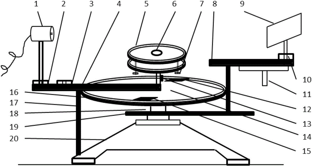
[0030] Install and fix the prepared double slits (the distance between the double slits can be 0.1mm-0.5mm) on a bracket, insert the bracket into the spare base 3, turn on the laser 1, let the laser pass through the double slits, adjust the light screen 9, The light passing through the double slits is projected onto the light screen 9 to form interference fringes at equal intervals. Fine-tune the light screen 9 so that the center of one of the interference fringes (dark) fringes coincides with the white vertical line in the light screen, and record the readings of α cursor 15 and β cursor 12 as α 1 and beta 1 , and then move the handle 11 so that when the white vertical line reaches the center of the adjacent bright (dark) stripe, record the readings α of the two verniers at this time 2 and beta 2 , so that the moving angle θ of the light screen 9 of the hand wheel can be ...

Embodiment 2

[0031] Embodiment 2-Single slit diffraction experiment and measurement of central bright pattern

[0032] Fix the prepared single slit (the width of the single slit is 0.1mm-0.3mm) on a bracket, insert the bracket into the spare base 3, turn on the laser 1, let the laser pass through the single slit, and adjust the light screen 9 so that The diffraction pattern is projected onto the light screen 9, and the light screen 9 is moved so that the crosshairs are fixed at the center of the +1-level dark fringe, and the readings of the two cursors α cursor 15 and β cursor 12 are read as α 1 and beta 1 , and then turn the light screen so that the intersection of the cross on the light screen is fixed at the center of the -1 level dark fringe, and the readings of α cursor 15 and β cursor 12 at this time are denoted as α 2 and beta 2 , using the formula Calculate the rotated angle θ, and the distance L between the light screen and the single slit can be read from the light source tra...

Embodiment 3

[0033] Embodiment 3-circle hole diffraction experiment and the measurement of Airy disk diameter

[0034] Install the prepared round hole (the diameter of the round hole is 0.1mm—0.5mm) on the bracket, insert the bracket into the spare base 3, let the light emitted by the laser 1 pass through the round hole, and adjust the light screen 9 so that it passes through the round hole The light is projected onto the light screen, forming a circular hole diffraction pattern. Fine-tune the light screen 9 so that the left edge of the Airy disk (that is, the center of the first-level dark ring stripe) coincides with the intersection of the crosshairs on the light screen, and record the readings of the two cursors α cursor 15 and β cursor 12 at this time denoted as α 1 and beta 1 , and then move the handle so that the intersection of the crosshairs on the light screen falls in the center of the right edge of the Airy disk (the center of the first-level dark ring stripe), record the read...


PUM


Abstract

The invention provides wave-optical comprehensive test instrument equipment. The wave-optical comprehensive test instrument equipment comprises a base provided with a center shaft, a light source track used for mounting an adjustable light source and a to-be-tested optical device and an alidade used for reading a rotation angle are arranged on the center shaft, a rotatable dial sheathes the periphery of the alidade, the dial is connected with an optical screen track which can synchronously rotate with the dial, and an adjustable optical screen used for receiving a light source signal is arranged on the optical screen. By adopting the wave-optical comprehensive test instrument equipment, demonstration and measurement of a plurality of experimental projects such as a double-slit interference experiment, a single slit diffraction experiment, a circular hole diffraction experiment, an optical grating diffraction experiment, a polarized light experiment, Malus law verification and Brewster angle determination can be completed, comprehensiveness is strong, and cost is saved.

Description

technical field [0001] The present invention mainly relates to a wave optics comprehensive testing instrument and equipment, in particular to a device capable of simultaneously measuring the width of bright (dark) fringes in double-slit interference experiments, the width of central bright fringes and other bright (dark) fringes in single-slit diffraction experiments. The width of the hole, the diameter of the Airy disk in the diffraction experiment of the circular hole, the size of the diffraction angle in the grating diffraction experiment, the verification of Marius' law, the determination of Brewster's angle, etc., and the demonstration of the above experimental items Function. Background technique [0002] In the early teaching, people used the light source, double slit, and light screen inserted into the optical bench to observe the phenomenon of double slit interference, but the width of the bright (dark) fringe of double slit interference could not be measured. Peop...

Claims


Application Information

Patent Timeline
Patent Type & Authority Applications(China)
IPC IPC(8): G01B11/04G01B11/08G01B11/26G09B23/22
CPCG01B11/046G01B11/08G01B11/26G09B23/22
Inventor 李淑青
Owner TAIYUAN INST OF TECH
Why Eureka
Try Eureka