Cone-beam CT rotation center calibration method based on the L0 norm minimization of reconstructed image gradient

A technology for reconstructing images and rotation centers, which is applied in the fields of biomedical imaging and non-destructive testing, and can solve the problems of inaccurate position of rotation centers, errors, and insignificant correction effects.

Active Publication Date: 2017-05-10
CHONGQING UNIV
View PDF4 Cites 6 Cited by
  • Summary
  • Abstract
  • Description
  • Claims
  • Application Information

AI Technical Summary

Problems solved by technology

[0003] In order to compensate the influence of the offset of the rotation center on the quality of the reconstructed image, Stephen et al. proposed a method of correcting the projection center by using the projected sinogram in the Journal of Nuclear Science in 1990 to calculate the offset of the rotation center, but this The correction effect of the method is not obvious when the system noise is large; Fu Jian et al. proposed in the Journal of Military Engineering in 2003 that the deviation of the focus is equivalent to the deviation of the rotation center, and different offsets are given to the ray source. The image is reconstructed and the offset corresponding to the reconstructed image with the highest signal-to-noise ratio and contrast is used to calculate the real offset of the rotation center. This method selects the signal-to-noise ratio and contrast to describe the accuracy of the rotation center, although there is a certain degree of effect but the calibration accuracy is limited
In 2006, Tong Liu et al. fixed a thin steel wire on the rotating platform at a certain distance from the rotation center in the Journal of Optical Engineering, and used the geometric relationship of the steel wire projection image to find the offset of the rotation center. This method The ...

Method used


Image

  • Cone-beam CT rotation center calibration method based on the L0 norm minimization of reconstructed image gradient
  • Cone-beam CT rotation center calibration method based on the L0 norm minimization of reconstructed image gradient
  • Cone-beam CT rotation center calibration method based on the L0 norm minimization of reconstructed image gradient

Examples


Embodiment Construction

[0056] The preferred embodiments of the present invention will be described in detail below with reference to the accompanying drawings.

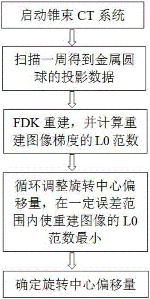
[0057] The rotation center offset parameter calibration method based on the minimization of the L0 norm of the reconstructed image gradient provided by the present invention, such as figure 1 As shown, it specifically includes the following steps:

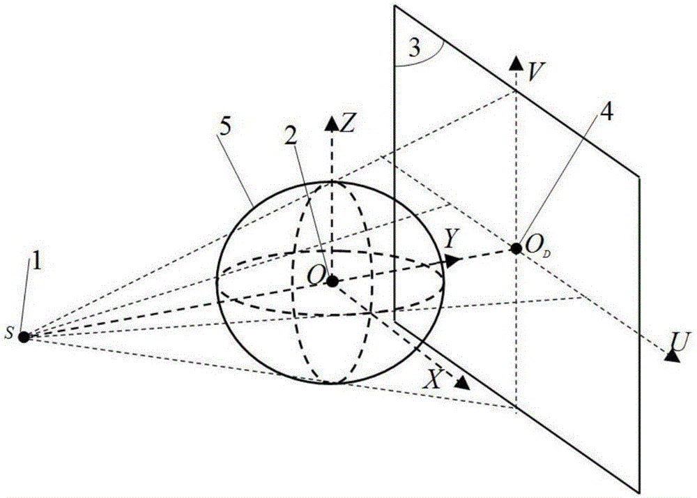
[0058] Step 1) Place the uniform metal sphere 5 on the rotating platform, and the ray source 1 and the detector 3 are on a circular orbit with the center of rotation 2 as the center, such as figure 2 As shown, start the cone beam CT system and scan to obtain the projection data of the metal sphere; when the cone beam CT system is started, take the rotation center O as the origin, take the line connecting the ray source and the rotation center as the Y axis, and point to the direction of the rotation center is the positive direction, the Z axis is perpendicular to the Y axis, and the vertical u...


PUM


Abstract

The invention relates to a cone-beam CT rotation center calibration method based on the L0 norm minimization of reconstructed image gradient. The method comprises the following steps: S1) placing even metal round balls on a rotation station; arranging the ray source and the detector on the circular track around the rotation center; initiating the cone-beam CT system; and scanning to obtain the projection data of the metal round balls; S2) according to the projection data of the metal round balls and the initial rotation center position of the cone-beam CT, using the FDK reconstruction algorithm and reconstruction software to obtain the reconstruction images of the metal round balls; and calculating the L0 norm of the reconstructed image gradient; S3) adjusting the offset parameters of the rotation center in the reconstruction software and reconstructing again to obtain the updated reconstruction images and calculating the L0 norm of the reconstructed image gradient; and S4) circularly adjusting the offset parameters of step 3 until the L0 norm of the reconstructed image gradient becomes the smallest within a certain error scope; and calibrating the offset parameters of the rotation center at this time as the desired calibration ones. The mode that the method uses can be manufactured simply. With only one time of cone-beam CT scanning, the imaging quality of the cone-beam CT system is increased.

Description

technical field [0001] The invention belongs to the technical field of biomedical imaging and non-destructive testing, and relates to a cone beam CT (Computed Tomography) rotation center calibration method based on the minimization of the L0 norm of the reconstructed image gradient. Background technique [0002] CT technology has been successfully applied in the field of non-destructive testing and has achieved great development. The cone-beam CT system with circular trajectory is mainly composed of three parts: X-ray source, rotating table and detector. The ideal imaging relationship of cone-beam CT system requires that the line connecting the ray source and the center of the detector (central ray) be perpendicular to the plane where the detector is located. , and perpendicular to the rotation axis of the turntable, the intersection point is the center of rotation. In the three-dimensional image reconstruction that requires high reconstruction image quality, the projection...

Claims


Application Information

Patent Timeline
IPC IPC(8): G06T11/00G01N23/04
CPCG01N23/04G01N2223/401G06T11/008
Inventor 曾理龚长城蔡玉芳王成祥
Owner CHONGQING UNIV
Why Eureka
Try Eureka