Supercharge Your Innovation With Domain-Expert AI Agents!

Ground-wall de-coupling connecting structure of common-emitter-structured transistor

A connection structure and decoupling technology, which is applied in the field of new ground wall decoupling connection structure, can solve the problems of deterioration of oscillator output power and oscillation frequency, deterioration of transistor performance, and small increase in oscillator output power, so as to improve output power and the effect of oscillation frequency

Active Publication Date: 2017-05-10
SOUTHEAST UNIV
View PDF5 Cites 2 Cited by
  • Summary
  • Abstract
  • Description
  • Claims
  • Application Information

AI Technical Summary

Problems solved by technology

The parasitic capacitance inside the transistor, especially the parasitic effect of the peripheral connection circuit of the transistor, often has a very adverse effect on the design of high-power and high-frequency frequency source circuits in the millimeter wave and submillimeter wave frequency bands
For example, at 200 GHz, for an ordinary connected transistor base and collector circuit, without decoupling treatment, the electromagnetic simulation software HFSS extracts the parasitic parameters and finds that the coupling capacitance between the base and collector via connections reaches The fF level is increased, which greatly deteriorates the performance of the transistor, which is directly reflected in the deterioration of the corresponding oscillator output power and oscillation frequency.
[0004] In order to solve the influence of the parasitic coupling of the peripheral connection structure of the millimeter-wave single transistor, it is often necessary to use a cascode structure, that is, a transistor with a cascode structure and a transistor with a cascode structure are superimposed and used, although this can reduce the circuit to a certain extent. The influence of parasitic coupling, but the cascode structure requires twice the emitter voltage, which is not conducive to the application in low-voltage environments, the power consumption is relatively high, and the output power of the oscillator is improved slightly
In addition, the cascode structure usually introduces additional noise that affects the phase noise of the oscillator

Method used


Image

  • Ground-wall de-coupling connecting structure of common-emitter-structured transistor
  • Ground-wall de-coupling connecting structure of common-emitter-structured transistor
  • Ground-wall de-coupling connecting structure of common-emitter-structured transistor

Examples


Embodiment Construction

[0022] The present invention will be further described below in conjunction with the accompanying drawings.

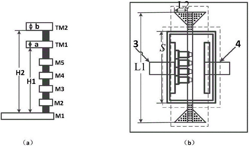
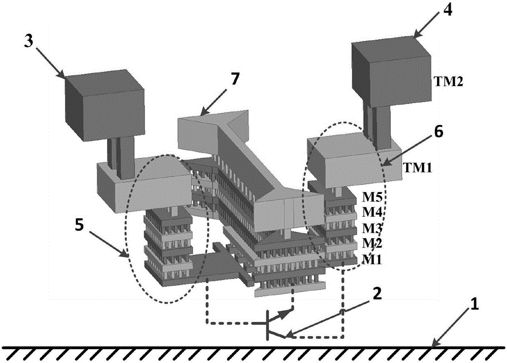
[0023] Such as figure 1 As shown, the basic structure of the present invention is a ground wall decoupling peripheral connection structure of a cascode transistor. Figure (a) is a metal and via layer distribution diagram of a silicon-based process, and figure (b) is a decoupling of the novel transistor. Top view of the coupling structure. For the transistor peripheral connection structure of the common emitter structure, a ground wall from M1 to TM1 is introduced, the ground wall is located between the base 3 and the collector 4, the length of the ground wall decoupling structure is L1, the length of the transistor is S, and the ground wall The length of the decoupling structure is at least twice the length of the transistor. In order to effectively reduce the coupling effect between the base and collector via connection arrays, a triangular structure is introduced at...


PUM


Abstract

The invention discloses a ground-wall de-coupling connecting structure of a common-emitter-structured transistor. The ground-wall de-coupling connecting structure comprises a transistor positioned in a substrate, a ground-wall de-coupling structure, and base and collector via hole connecting arrays; a thin metal layer close to the substrate and a thick metal layer on the top layer are provided by a silicon-based process, so that the top layer metal and the transistor positioned in the substrate are connected by requiring the via hole arrays; the via hole arrays are relatively close to each other at the height of about 10[mu]m; for millimeter-wave and submillimeter-wave oscillator circuits at frequency greater than 100GHz, the coupling stray capacitance between two rows of the via hole arrays can reach a fF magnitude, so that great influence is generated to the performance of the oscillators; and by introducing an emitter ground-wall de-coupling structure, the ground-wall structure length is optimized, and coupling between the base and the collector via hole arrays of the transistor can be eliminated, so that the output power and the output frequency of submillimeter-wave oscillators can be greatly improved.

Description

technical field [0001] The present invention relates to a new type of ground wall decoupling connection structure, specifically a ground wall decoupling connection structure manufactured by semiconductor integrated circuit technology and using common emitter structure transistors to improve the output power and oscillation of millimeter wave and submillimeter wave oscillators A new type of transistor peripheral connection structure for frequency. Background technique [0002] The lower frequency ranges of the electromagnetic spectrum are currently allocated to many radio applications such as radio, television, satellite communications, mobile telephony, military applications, and radio astronomy, among others. With the further development of radio technology, the spectrum resources in the low-frequency band are already very crowded. For the needs of future communication applications, the channel capacity of the low-frequency band has been difficult to meet the requirements. ...

Claims


Application Information

Patent Timeline
IPC IPC(8): H01L23/66H03B5/12
CPCH01L23/66H01L2223/6616H03B5/1231
Inventor 陈继新周培根严蘋蘋侯德斌洪伟
Owner SOUTHEAST UNIV
Features
  • R&D
  • Intellectual Property
  • Life Sciences
  • Materials
  • Tech Scout
  • Unparalleled Data Quality
  • Higher Quality Content
  • 60% Fewer Hallucinations
Learn More