Phase change capsule suspension/floating heat management and cold starting system

A phase change capsule and thermal management technology, which is applied in the fields of fuel cell heat exchange, fuel cell additives, fuel cells, etc. The effect of prolonging the cooling time

Active Publication Date: 2017-05-10
TSINGHUA UNIV
View PDF5 Cites 18 Cited by
  • Summary
  • Abstract
  • Description
  • Claims
  • Application Information

AI Technical Summary

Problems solved by technology

The membrane material needs to exhibit proton conduction characteristics in the presence of water, which limits the operat

Method used


Image

  • Phase change capsule suspension/floating heat management and cold starting system
  • Phase change capsule suspension/floating heat management and cold starting system
  • Phase change capsule suspension/floating heat management and cold starting system

Examples


Embodiment 1

[0036] 1. Heat and melt 1000g of paraffin wax to obtain a paraffin wax solid-liquid phase change material, which is ready for use;

[0037] 2. Take 500ml of ethanol as the gas-liquid phase change material and set it aside;

[0038] 3. Using polyethylene as the material, use a film making machine to prepare a number of polyethylene film materials, the thickness of which is 120 μm, and set aside;

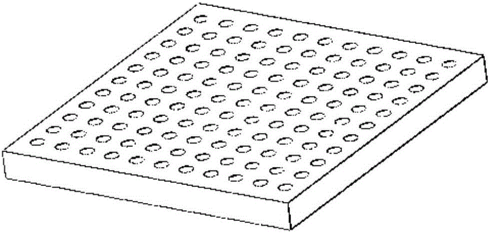
[0039] 4. Put the polyethylene film made in step 3 on the surface of the concave mold, the diameter of the hemispherical concave surface is 2.1mm, such as figure 1 shown;

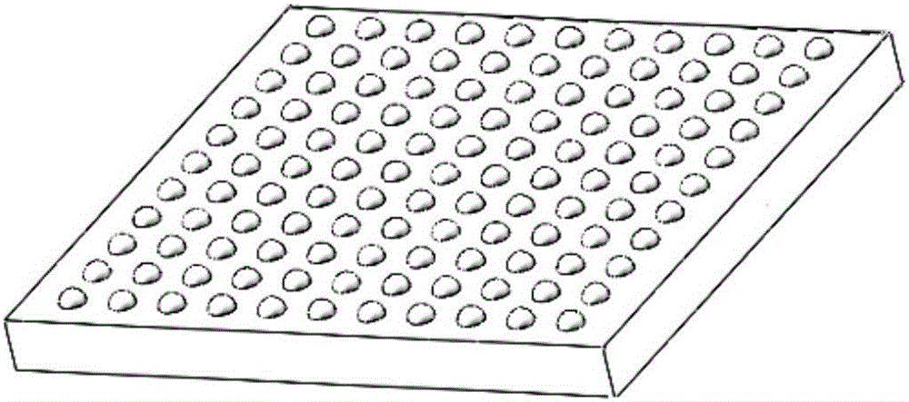
[0040] 5. Put the convex mold upside down on the surface of the concave mold with polyethylene film, the diameter of the hemispherical convex surface is 2mm, such as figure 2 As shown, the polyethylene film is pressed out of the hemispherical concave groove;

[0041] 6. Use a dispensing machine to inject the phase change materials in step 1 and step 2 into the hemispherical concave grooves obtained in step 5. A...

Embodiment 2

[0050] 1. Heat and melt 2Kg of paraffin wax to obtain a paraffin wax solid-liquid phase change material, ready to use;

[0051] 2. Take 1L of methanol as the gas-liquid phase change material and set it aside;

[0052] 3. Using polypropylene as the material, use a film making machine to prepare several polypropylene film materials, the thickness of which is 100 μm, and set aside;

[0053] 4. Place the polypropylene film made in step 3 on the surface of the concave mold, the diameter of the hemispherical concave surface is 4.1mm, such as figure 1 shown;

[0054] 5. Invert the convex mold on the surface of the concave mold with polypropylene film, the diameter of the hemispherical convex surface is 4mm, such as figure 2 As shown, the polypropylene film is pressed out of the hemispherical concave groove;

[0055] 6. Use a dispensing machine to inject the phase change materials in step 1 and step 2 one by one into the hemispherical concave groove obtained in step 5. The mass of...


PUM

PropertyMeasurementUnit
Average densityaaaaaaaaaa
Particle sizeaaaaaaaaaa
Diameteraaaaaaaaaa

Abstract

The invention relates to a phase change capsule suspension/floating heat management and cold starting system. A suspension/floating phase change capsule and cooling liquid combined system is installed in a cooling liquid box, the density of suspension/floating phase change capsules is equivalent to that of the cooling liquid, so that the suspension/floating phase change capsules can be suspended in the cooling liquid, the density is decreased after the heat absorption, and the suspension/floating phase change capsules are floated at the surface of the cooling liquid; and the cooling liquid box is connected with a fuel cell stack to form a cooling liquid circulating loop. The suspension/floating phase change capsule and cooling liquid combined system exchanges the heat with the fuel cell stack, when a fuel cell works, the suspension/floating phase change capsules absorb a great number of heat, so that the cooling liquid circularly cools the fuel cell and stores the heat; and when the fuel cell stops working, the suspension/floating phase change capsules release the phase change latent heat to preserve the heat of the fuel cell stack, and the preheating time of the fuel cell when in cold starting can be shortened, so that a cooling and heat preservation effect for the fuel cell can be achieved, and the heat management and cold starting system of the fuel cell is optimized.

Description

technical field [0001] The invention belongs to the technical field of fuel cell thermal management and cold start, and in particular relates to a phase change capsule suspension / floating thermal management and cold start system. Background technique [0002] At present, the traditional fossil energy is becoming exhausted day by day, and the large-scale consumption of fossil energy has caused serious environmental pollution, so an environmentally friendly new energy is urgently needed. Hydrogen energy is a kind of clean new energy. Proton exchange membrane fuel cell uses hydrogen as fuel, which can directly convert the chemical energy in hydrogen into electrical energy, and only discharges water during the power generation process. It is a zero-emission power generation device using hydrogen energy. . The fuel cell has been widely used in fields such as stationary power stations, portable power supplies, and automobile drive power supplies. [0003] At present, one of the ...

Claims


Application Information

Patent Timeline
IPC IPC(8): H01M8/04H01M8/04007H01M8/04029H01M8/10
CPCH01M8/04H01M8/04007H01M8/04029H01M8/10Y02E60/50
Inventor 王树博谢晓峰
Owner TSINGHUA UNIV
Why Eureka
Try Eureka