Flyback switching power supply

A switching power supply and flyback technology, applied in electrical components, adjusting electrical variables, instruments, etc., can solve the problems of complex process, low primary winding inductance, discontinuous input current of flyback switching power supply, etc. High efficiency and good EMI performance

Active Publication Date: 2017-05-10
MORNSUN GUANGZHOU SCI & TECH
View PDF2 Cites 16 Cited by
  • Summary
  • Abstract
  • Description
  • Claims
  • Application Information

AI Technical Summary

Problems solved by technology

In fact, the low-voltage DC / DC switching power supply adopts the flyback topology. This is because at low voltage, the input current of the flyback switching power supply is discontinuous, the ripple is large, and the requirements for the previous power supply equipment are relatively high. High; the output current is not continuous, the ripple is very large, and the capacity of the filter capacitor behind is required to be high; especially when the input voltage is low, because the excitation current becomes larger, the primary winding must be wound with multiple strands; The inductance of the side winding is also low, and it often happens that the calculated number of turns cannot be tiled from the left to the right of the wire slot that is full of the skeleton. Especially when the working voltage is high, the sandwich series winding method can be used. Downside, it is forced to adopt the sandwich parallel winding method. Since the two primary windings are not on the same layer, there is a leakage inductance between the two primary windings. This leakage inductance will cause losses, thereby reducing the efficiency of the switching power supply. , the problem caused by the leakage inductance between two parallel primary windings:
[0004] 1) During excitation, due to the existence of leakage inductance, the induced voltage difference has a pressure difference on the leakage inductance, causing a non-negligible loss. This is easier to understand: if the number of turns of two parallel primary windings is one turn, it is equivalent to existence This turn-to-turn short circuit is just a short circuit through the DC internal resistance of two parallel primary windings. Relatively speaking, the loss is not as large as a real inter-turn short circuit.
[0005] 2) During demagnetization, that is, the rectifier diode on the secondary side is turned on, and the output filter capacitor is continuously charged. At this time, the reflected voltage is induced on the primary side, and the two parallel primary windings will induce unequal voltages. The internal resistance is low, and the current caused by the induced unequal voltage is not small, which causes loss and large electromagnetic interference
[0006] 3) If the third winding is used to demagnetize, which of the two parallel primary windings is the third winding? Only two tertiary windings can be used, which are respectively wound in parallel with the two primary windings connected in parallel, and then connected in parallel to form a "third winding". voltage, causing loss and large electromagnetic interference
[0007] In fact, for the common demagnetization of the third winding, the advantage is lossless demagnetization and high efficiency, but the selection of the wire diameter of the third winding is also a problem: the selection is relatively thin, and it is troublesome to wind in parallel with the primary winding, and it is easy to The thin wire is broken; if the wire diameter is selected to be the same as that of the primary winding, the cost will be high

Method used


Image

  • Flyback switching power supply
  • Flyback switching power supply
  • Flyback switching power supply

Examples


no. 1 example

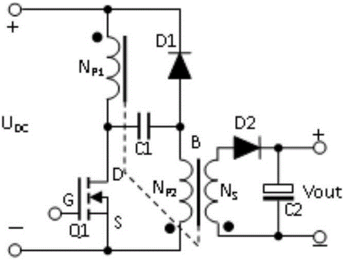
[0028] figure 2 It shows the principle diagram of the flyback switching power supply of the first embodiment of the present invention, including a transformer B, an N-channel field effect transistor Q1, a second capacitor C2, a first diode D1, and a second diode D2 , the transformer B includes the first primary winding N P1 , the second primary winding N P2 and the secondary winding N S , secondary winding N S The opposite end is connected to the anode of the second diode D2, and the cathode of the second diode D2 is connected to one end of the second capacitor C2 to form a positive output, which is the + end of Vout in the figure, and the secondary winding N S The end with the same name is connected to the other end of the second capacitor C2 to form a negative output, which is the - end of Vout in the figure; the input DC power supply U DC (hereinafter also referred to as DC power supply U DC , Power U DC , or U DC ) of the positive terminal + at the same time with t...

no. 2 example

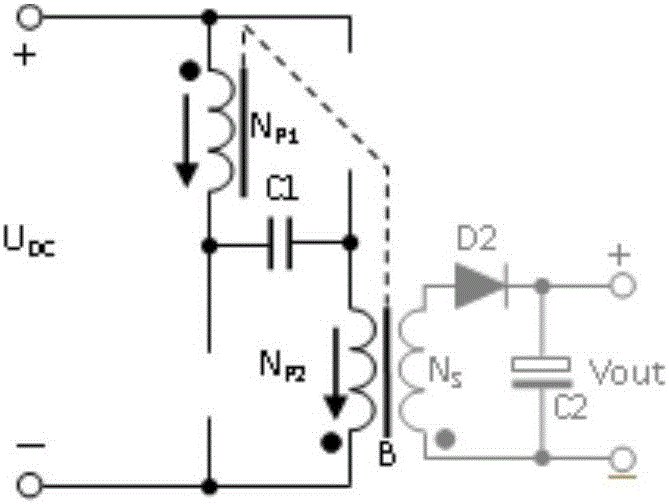
[0053] The present invention also provides an equivalent solution to the above-mentioned first embodiment, corresponding to solution 2, see image 3 , a flyback switching power supply, including a transformer B, an N-channel field effect transistor Q1, a second capacitor C2, a first diode D1, a second diode D2, and the transformer B includes a first primary winding N P1 , the second primary winding N P2 and the secondary winding N S , secondary winding N S The opposite end is connected to the anode of the second diode D2, and the cathode of the second diode D2 is connected to one end of the second capacitor C2 to form a positive output, which is the + end of Vout in the figure, and the secondary winding N S The end with the same name is connected to the other end of the second capacitor C2 to form a negative output, which is the - end of Vout in the figure; the input DC power supply U DC The positive terminal + of the N-channel field effect transistor Q1 and the second prim...

no. 3 example

[0070] see Figure 4, is also the aforementioned scheme three, a flyback switching power supply, including a transformer B, a P-channel field effect transistor Q1, a second capacitor C2, a first diode D1, a second diode D2, and the transformer B includes The first primary winding N P1 , the second primary winding N P2 and the secondary winding N S , secondary winding N S The opposite end is connected to the anode of the second diode D2, and the cathode of the second diode D2 is connected to one end of the second capacitor C2 to form a positive output, which is the + end of Vout in the figure, and the secondary winding N S The end with the same name is connected to the other end of the second capacitor C2 to form a negative output, which is the - end of Vout in the figure; the input DC power supply U DC The negative end of - at the same time with the first primary winding N P1 The opposite terminal and the anode of the first diode D1 are connected, and the first primary wi...


PUM


Abstract

The invention discloses a flyback switching power supply. On the basis of a common three-winding absorption flyback converter, the dotted terminal of NP1 in a transformer B is connected to a power supply, the dotted terminal of NP2 of a second primary side winding is grounded, double-wire winding of NP1 and NP2 is guaranteed, one capacitor C1 is added, one end of C1 is connected with the heteronymous terminal of NP1, and the other end of C1 is connected with the heteronymous terminal of NP2, so that NP1 and NP2 are excited when Q1 is conducted in a saturated manner, energy is output from secondary side NS when Q1 is disconnected, and energy of leakage inductance is losslessly adsorbed through D1; the flyback switching power supply is suitable for working under low voltage, and the utilization rate and current density of primary side winding are improved, so that the power density is large, relatively large leakage inductance between primary side and secondary side is permitted, and the conversion efficiency is high.

Description

technical field [0001] The invention relates to the field of switching power supplies, in particular to a flyback switching power supply. Background technique [0002] At present, switching power supplies are widely used. For occasions where the input power is below 75W and the power factor (PF, PowerFactor, also known as power factor) is not required, the flyback (Fly-back) switching power supply has attractive advantages: circuit topology Simple, wide input voltage range. Due to the small number of components, the reliability of the circuit is relatively high, so it is widely used. For convenience, many documents are also called flyback switching power supply, flyback power supply, and flyback converter. In Japan and Taiwan, they are also called flyback converter, flyback switching power supply, and flyback power supply. Common topologies for AC / DC converters such as figure 1 As shown, the prototype of this figure comes from page 60 of "Switching Power Converter Topolog...

Claims


Application Information

Patent Timeline
Patent Type & Authority Applications(China)
IPC IPC(8): H02M3/335
CPCH02M3/335
Inventor 王保均
Owner MORNSUN GUANGZHOU SCI & TECH
Why Eureka
Try Eureka