
A converter system and a stator DC excitation motor with the system

A converter system, DC excitation technology, applied in AC motor control, electronic commutation motor control, conversion of AC power input to DC power output, etc., can solve the problem of not achieving optimal utilization of power devices and optimal selection of power devices , can not meet the control requirements and other problems, to achieve optimal utilization, improve power density, life balance effect

Active Publication Date: 2019-06-18
HUAZHONG UNIV OF SCI & TECH
View PDF7 Cites 0 Cited by
  • Summary
  • Abstract
  • Description
  • Claims
  • Application Information

AI Technical Summary

Problems solved by technology

[0005] (1) The motor driver topology can only drive 3n-phase motors, and cannot drive any n-phase motors
[0006] (2) The motor driver topology and its control algorithm can only realize traditional SVPWM modulation, and the output current waveform can only be a sine wave without DC bias
For new motors whose stator side current requires DC bias, this algorithm cannot meet the control requirements
[0007] (3) The topology of the motor driver does not optimize the selection of power devices, resulting in redundant waste of power devices, failure to achieve optimal utilization of power devices, low power density of the system, and poor economy

Method used


Image

  • A converter system and a stator DC excitation motor with the system
  • A converter system and a stator DC excitation motor with the system
  • A converter system and a stator DC excitation motor with the system

Examples


Embodiment Construction

[0034] In order to make the object, technical solution and advantages of the present invention clearer, the present invention will be further described in detail below in conjunction with the accompanying drawings and embodiments. It should be understood that the specific embodiments described here are only used to explain the present invention, not to limit the present invention. In addition, the technical features involved in the various embodiments of the present invention described below can be combined with each other as long as they do not constitute a conflict with each other.

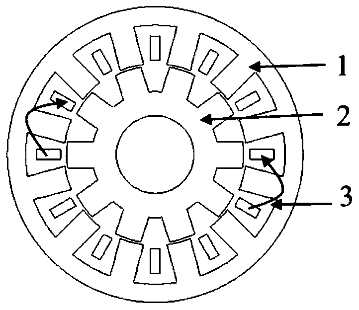
[0035] figure 1 It is the structure of the DC bias sinusoidal current motor of the stator DC excitation motor according to the embodiment of the present invention. Such as figure 1 As shown, the DC bias sinusoidal current motor includes a stator 1, a rotor 2, and a winding 3, as well as other common structural parts of the motor such as a shaft, a casing, an end cover, and a position encoder. ...


PUM


Abstract

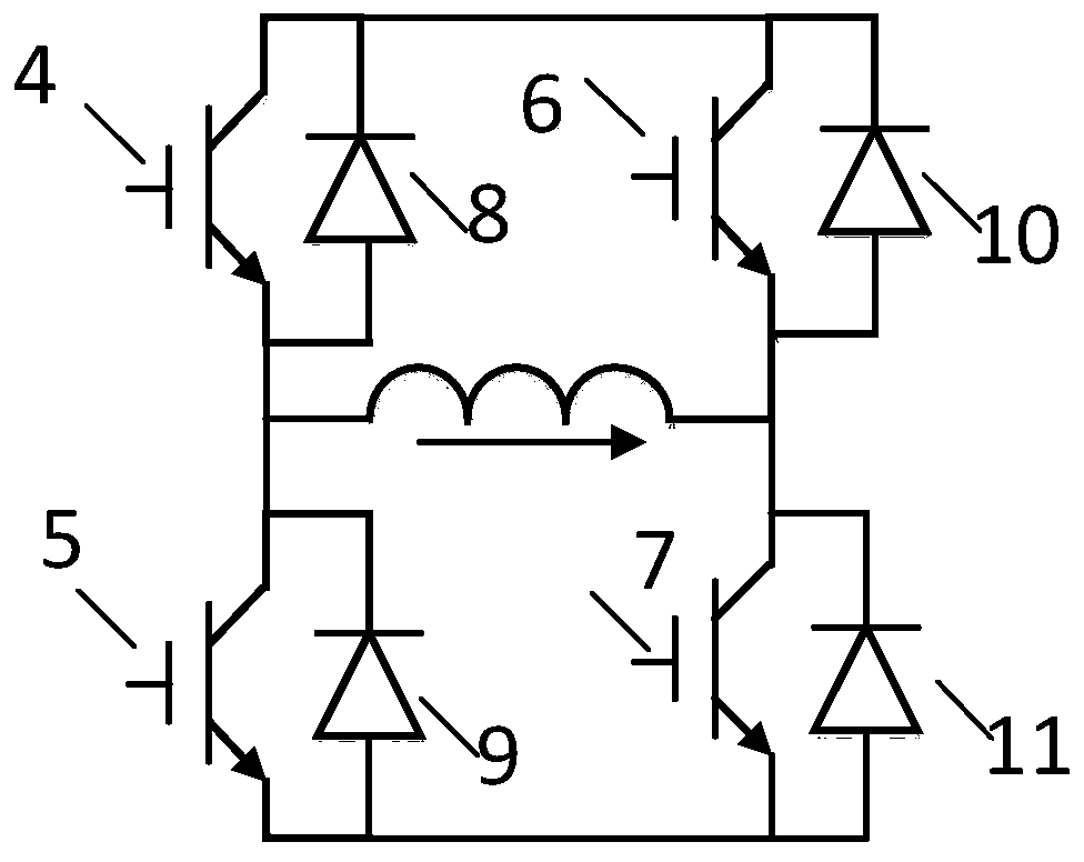
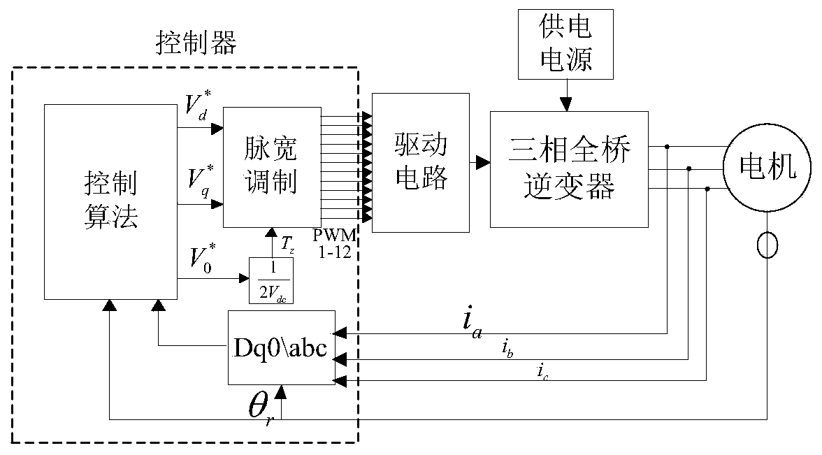
The invention discloses a converter system, which includes a power supply, a stator DC excitation motor and a controller, the controller includes a converter module, and the converter module includes: N groups of single-phase motors with asymmetric capacity The converter topology composed of a full-bridge inverter circuit is used to control the current of the DC excitation motor. The asymmetric capacity single-phase full-bridge inverter circuit topology includes two large-capacity switching devices, two large-capacity Diode devices, two small-capacity switching devices, two small-capacity diode devices; and an N-phase drive circuit composed of N-chip drive chips and their peripheral components, used to drive the converter topology, thereby realizing control of the DC excitation motor current. The invention also discloses a stator DC excitation motor with the converter system. The converter system of the present invention realizes optimal torque density, increases the power density of the converter, and reduces the cost of the motor control system.

Description

technical field [0001] The invention belongs to the field of inverse AC motors and drive control, and more specifically relates to a converter system and a stator DC excitation motor with the system. Background technique [0002] The application of power electronic converters as controllers is the main method of modern electric drives. Permanent magnet motors have the advantages of high power density, high efficiency, and high power factor, but the cost of permanent magnet motors is relatively high. The traditional switched reluctance motor has a simple structure and low cost, but due to its unique power supply method, there is a large current peak at the moment the switch is turned off, so the vibration and noise of the motor are very large. In addition, the torque ripple of the motor Also larger. These shortcomings affect the use of switched reluctance motors in some occasions that require high vibration and noise. In recent years, some scholars have proposed a vernier ...

Claims


Application Information

Patent Timeline
Patent Type & Authority Patents(China)
IPC IPC(8): H02P27/08H02P21/22H02M7/5387
CPCH02M7/5387H02P27/08H02M1/0067
Inventor 蒋栋李安贾少锋曲荣海李大伟孔武斌高子晗
Owner HUAZHONG UNIV OF SCI & TECH
Learn More