A sludge separation device

A kind of oil sludge separation and oil sludge technology, which is applied in the direction of sludge treatment, water/sludge/sewage treatment, natural water treatment, etc., can solve the problems of frequent replacement of filter cloth, troublesome operation of filter press, high labor intensity, etc., to achieve Low cost of long-term use, low cost of dosing, and high labor intensity

Active Publication Date: 2020-06-12
陕西航天德林科技集团有限公司
View PDF4 Cites 0 Cited by
  • Summary
  • Abstract
  • Description
  • Claims
  • Application Information

AI Technical Summary

Problems solved by technology

The operation of the filter press is cumbersome, labor-intensive, the filter cloth needs to be replaced frequently, and the processing capacity is small at the same time

Method used


Image

  • A sludge separation device

Examples


Embodiment Construction

[0029] In order to make the purpose, technical solutions and advantages of the embodiments of the present invention clearer, the technical solutions in the embodiments of the present invention will be clearly and completely described below in conjunction with the drawings in the embodiments of the present invention. Obviously, the described embodiments It is a part of embodiments of the present invention, but not all embodiments. Based on the embodiments of the present invention, all other embodiments obtained by persons of ordinary skill in the art without making creative efforts belong to the protection scope of the present invention.

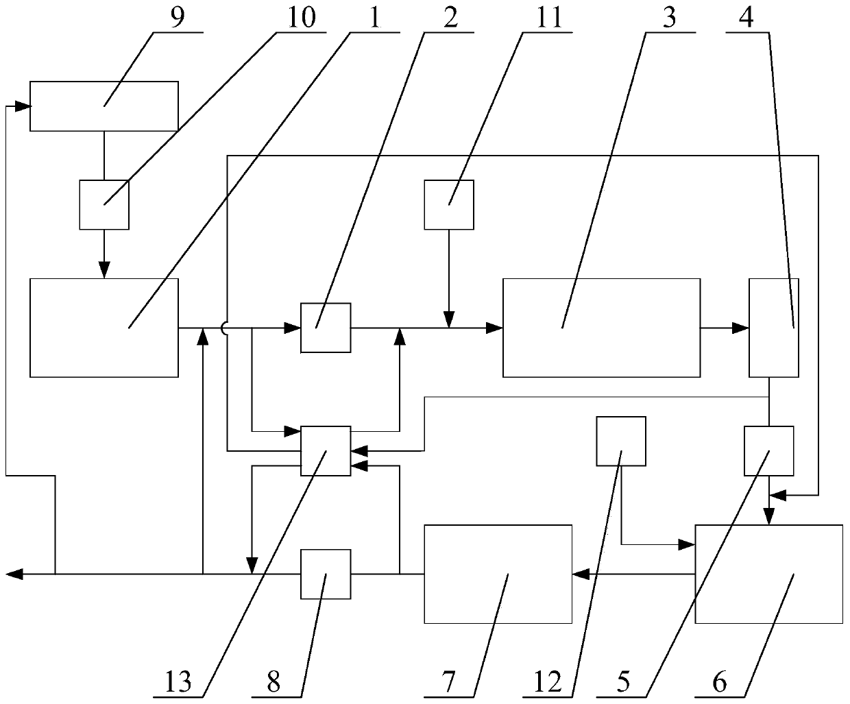
[0030] Please refer to figure 1 , figure 1 Schematic diagram of the structure of the oil sludge separation device provided by the embodiment of the present invention.

[0031] The sludge separation device provided in the embodiment of the present invention includes a sludge tank 1, a first pump body 2, a vibrating screen 3, a first storage ...


PUM


Abstract

The invention discloses an oil sludge separating device. The oil sludge separating device comprises an oil sludge pond, a first pump body, a vibrating screen, a first storage tank, a second pump body, a centrifugal machine, a second storage tank and a third pump body which are communicated with one another in sequence. Oil sludge is fed into the vibrating screen from the oil sludge pond through the first pump body for primary separation. A solid-phase object after primary separation is conveyed out, a liquid-phase object after primary separation enters the first storage tank to be deposited, and the deposited liquid-phase object is fed into the centrifugal machine through the second pump body for secondary separation. A solid-phase object after secondary separation is conveyed out, and a liquid-phase object after secondary separation enters the second storage tank. A density tester is arranged in the second storage tank, and a qualified liquid-phase object detected by the density tester is conveyed through the third pump body. The oil sludge separating device provided by the invention can improve the separating efficiency.

Description

technical field [0001] The invention relates to the technical field of oil sludge separation, in particular to an oil sludge separation device. Background technique [0002] The oil sludge produced in the production process of the gas field contains various impurities. When it is transported to the treatment plant, the amount of oil sludge to be treated is large and the solid impurities are large, resulting in high treatment costs. As the traditional activated sludge process is widely used in the treatment of urban sewage and industrial wastewater, the amount of excess sludge is also increasing. Therefore, the development of a new sludge reduction process is an urgent problem to be solved. Sludge Process reduction means that in the process of sewage treatment, by changing the operating conditions of the existing process or adopting certain technical means, the sludge output is reduced without affecting the sewage treatment effect, so the sludge reduction Chemical treatment ...

Claims


Application Information

Patent Timeline
Patent Type & Authority Patents(China)
IPC IPC(8): C02F11/127C02F103/36
CPCC02F11/127C02F2103/365C02F2209/01C02F2209/02C02F2301/043C02F2301/046C02F2303/14
Inventor 林忠灿林宗南陈云峰林晓威梁娜娜苑长忠林曼真
Owner 陕西航天德林科技集团有限公司
Why Eureka
Try Eureka