Prefabricated combined corrugated steel web T girder bridge

A corrugated steel web, combined technology, used in bridges, bridge parts, bridge materials, etc., can solve the cracking of the interface between the post-cast concrete and the precast part, the stress of the bridge structure during the use stage of the completed bridge, and the different shrinkage of concrete. Changes and other problems, to achieve the effect of good structural integrity, improved construction efficiency and service life, and light weight

Active Publication Date: 2017-05-17
HENAN PROVINCIAL COMM PLANNING & DESIGN INST CO LTD +1
View PDF6 Cites 8 Cited by
  • Summary
  • Abstract
  • Description
  • Claims
  • Application Information

AI Technical Summary

Problems solved by technology

[0004] 1. Wet joints are generally narrow, and the construction space is small. Binding the steel bars at the wet joints is time-consuming and labor-intensive. The bottom edge of the wet joints of the roof needs to support the formwork, and the on-site construction is difficult;
[0005] 2. There is a difference in the pouring age of the concrete at the joint between the wet joint and the prefabricated beam, resulting in different shrinkage and creep of the old and new concrete, which is likely

Method used


Image

  • Prefabricated combined corrugated steel web T girder bridge
  • Prefabricated combined corrugated steel web T girder bridge
  • Prefabricated combined corrugated steel web T girder bridge

Examples


Example Embodiment

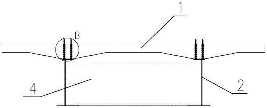
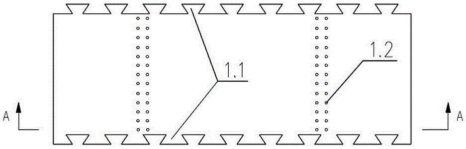
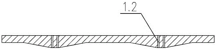
[0037] Such as figure 1 As shown, the prefabricated composite corrugated steel web T-beam bridge of the present invention includes a reinforced concrete top slab 1 and a longitudinal beam 2 arranged under the reinforced concrete top slab 1. The reinforced concrete top slab 1 is composed of multiple pieces with the same width as the bridge deck The strip plates are spliced ​​together. The splicing surfaces of two adjacent strip plates are provided with matching assembling slots 1.1. The strip plates are provided with insertion holes 1.2 corresponding to the position of the longitudinal beam 2; It is a set of corrugated steel webs 2.3 welded with top edge steel plate 2.1 and bottom edge steel plate 2.2. The top edge steel plate 2.1 is welded with connecting nails 2.4. The connecting nails 2.4 pass through the insertion hole 1.2 and pass through the pouring concrete 3 and the strip. The corrugated steel webs 2.3 are welded with a plurality of transverse steel partitions 4 arranged ...


PUM

PropertyMeasurementUnit
Widthaaaaaaaaaa

Abstract

The invention discloses a prefabricated combined corrugated steel web T girder bridge which comprises a reinforced concrete top plate and longitudinal beams arranged under the reinforced concrete top plate, wherein the reinforced concrete top plate is formed in the manner of splicing a plurality of bar-shaped plates in equal width with a girder bridge deck; mutually matched splicing slots are formed on the splicing surfaces of two adjacent bar-shaped plates; inserting holes corresponding to the positions of the longitudinal beams are formed on the bar-shaped plates; the longitudinal beams are arranged as a set of corrugated steel webs which are welded with top edge steel plates and bottom edge steel plates; connecting bolts are welded on the top edge steel plates; the connecting bolts are penetrated through the inserting holes and are integrally fixed with the bar-shaped plates in the manner of concreting; a plurality of horizontal steel separating plates which are arrayed along the longitudinal direction of the bridge are welded between the corrugated steel webs at intervals. A method for combining the prefabricating with the on-site assembling is adopted in a construction process. Thus, the prefabricated combined corrugated steel web T girder bridge provided by the invention has the advantages of simple structure, convenience in construction, low maintenance cost and capability of greatly increasing construction efficiency and service life.

Description

technical field [0001] The invention relates to the technical field of road and bridge construction, in particular to a prefabricated combined corrugated steel web T-beam bridge. Background technique [0002] T-girder bridge with corrugated steel web is a new type of steel-concrete composite structure bridge. Generally, a number of T-shaped assembly units composed of reinforced concrete roof and corrugated steel web longitudinal beam are prefabricated in the prefabrication yard, and then the T is assembled on site. The single-span girder body that meets the bridge width requirements is formed by horizontal splicing of the type assembly units, and then the adjacent span girder bodies are assembled vertically to complete the construction of the entire T-beam bridge. Because corrugated steel web T-girder bridge adopts two materials of corrugated steel plate and concrete, which combines the advantages of high compressive strength of concrete and high shear strength of corrugated...

Claims


Application Information

Patent Timeline
IPC IPC(8): E01D21/00E01D19/12E01D2/00E01D101/26
CPCE01D2/00E01D19/125E01D21/00E01D2101/268
Inventor 吴继峰杜战军汤意王鑫张军伟黄冉
Owner HENAN PROVINCIAL COMM PLANNING & DESIGN INST CO LTD
Why Eureka
Try Eureka