
Engineering geological drilling construction method based on thin-walled drilling tool

A technology of engineering geology and construction methods, applied in drilling equipment and methods, earthwork drilling, drilling equipment, etc. Accurate test results and fast drilling speed

Active Publication Date: 2017-05-17
ZHUHAI EAGLER SPECIALTY DRILLING EQUIP CO LTD
View PDF7 Cites 6 Cited by
  • Summary
  • Abstract
  • Description
  • Claims
  • Application Information

AI Technical Summary

Problems solved by technology

[0003] At present, the most widely used engineering geological drilling is to use a vertical shaft drilling rig (such as XY-1 or XY-2 type) and a single-tube drilling tool to drill with a cemented carbide drill bit mechanically, without sending water and dry drilling, and the footage is 0.5~ 2 meters, lift a big drill, take the core and carry out the standard penetration test, you need to lift the whole set of drill pipe and drilling tools out of the hole. The biggest advantage of this method is low cost and simple operation, but The limitations and shortcomings are also very obvious. Due to the single-pipe drilling, the disturbance to the soil layer is large, and it is difficult to extract undisturbed soil samples in complex strata, resulting in poor core quality; Or put down the entire drill pipe and drilling tools, it is easy to damage the hole wall, and often occurs such as block dropping and hole collapse, resulting in drill sticking accidents; in addition, during the standard penetration test, the drill pipe is elastically deformed by the hammer and easily hits the hole wall, which affects the stability of the hole wall, and the friction between the drill pipe and the hole wall affects the test accuracy

Method used


Image

  • Engineering geological drilling construction method based on thin-walled drilling tool
  • Engineering geological drilling construction method based on thin-walled drilling tool

Examples


Embodiment Construction

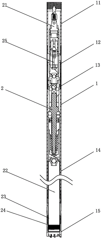
[0025] Such as figure 1 As shown, the drilling tool in the present invention is a single-action double-tube thin-walled drilling tool, including an outer tube assembly 1 and an inner tube assembly 2 inserted in the outer tube assembly 1, and the outer tube assembly 1 includes The bullet stopper 11, the bullet chamber 12, the seat ring 13, the outer tube 14, the reamer 15 and the thin-walled drill bit 16 are sequentially connected from top to bottom, and the minimum inner diameter of the outer tube assembly 1 is not less than 56mm , the thin-walled drill bit 16 is made of cemented carbide, or a composite drill bit or a diamond-impregnated drill bit, with an outer diameter of 75.7 mm and an inner diameter of 56 mm. The inner tube assembly 2 includes sequentially connected from top to bottom Drilling tool head assembly 21, rock core pipe 22, jump ring seat 23 and jump ring 24, seat ring 13 can limit support drilling tool head assembly 21, and drilling tool head assembly 21 is pro...


PUM


Abstract

The invention discloses an engineering geological drilling construction method based on a thin-walled drilling tool. According to the engineering geological drilling construction method based on the thin-walled drilling tool, a single rotary double-tube drilling tool is adopted, pressing drilling is conducted in rotation, the full-hole follow-pipe drilling speed is quick, slurry consumption is little, a rock core tube is kept to be in a non-rotation state, and disturbance on a soil layer is small; and when the drilling depth reaches the length of the rock core tube, an oil cylinder lifts the whole drilling machine away from the hole bottom for a section of distance to break off a rock core. The core taking quality is high, and an undisturbed soil sample can be extracted; during core taking and a standard penetration test, a drill rod and an outer tube assembly are kept in a drilled hole to be still all the time, the hole wall is protected, and damage, caused by repeatedly drill pipe lifting, to the hole wall is avoided; and meanwhile, friction between a test rod and the hole wall is reduced, uncertain factors are reduced, and the test result is more accurate.

Description

technical field [0001] The invention relates to the technical field of engineering geological drilling, in particular to an engineering geological drilling construction method based on a thin-walled drilling tool. Background technique [0002] Engineering geological drilling is to use drilling tools to drill into the formation according to certain purposes and requirements, and take out cores and soil samples to find out the geological conditions and foundation bearing capacity. This requires drilling into the topsoil layer and has special sampling requirements, and also requires It is one of the purposes of engineering drilling to carry out special testing work in boreholes and take undisturbed soil samples. This is to measure the physical and mechanical properties of the natural structure of the soil, such as capacity, density, temperature, shear strength, and compressibility coefficient. Describe the characteristics of rock and soil and determine the bearing capacity and ...

Claims


Application Information

Patent Timeline
Patent Type & Authority Applications(China)
IPC IPC(8): E21B7/00E21B25/00E21B47/00
CPCE21B7/00E21B25/00
Inventor 王坚刘绪勇
Owner ZHUHAI EAGLER SPECIALTY DRILLING EQUIP CO LTD
Learn More