Temperature-controlled hydraulic system for top drive drilling rig

A technology for hydraulic systems and drilling rigs, applied in the directions of fluid pressure actuation system components, mechanical equipment, fluid pressure actuation devices, etc., can solve the problems of difficulty in adapting to high and low temperature environments, single heating form and control, and high cost of temperature control systems. Achieve the effect of strengthening the heating and heat preservation effect, improving the reliability of the system and the convenience of maintenance, and strengthening the heating effect.

Active Publication Date: 2018-05-01
SHANGHAI LANSHI HEAVY IND MACHINERY
View PDF5 Cites 0 Cited by
  • Summary
  • Abstract
  • Description
  • Claims
  • Application Information

AI Technical Summary

Problems solved by technology

At present, the technical means of temperature-controlled hydraulic systems for top drive drilling rigs mainly have the following disadvantages: the heating form and control are single, and electric control heating is usually installed, the reliability is not high, and it is difficult to adapt to the requirements of high and low temperature environments; the electronic components of oilfield equipment require Explosion-proof, so the cost of general temperature control system is higher

Method used


Image

  • Temperature-controlled hydraulic system for top drive drilling rig

Examples


Embodiment Construction

[0013] A preferred embodiment will be given below, and the present invention will be described more clearly and completely in conjunction with the accompanying drawings.

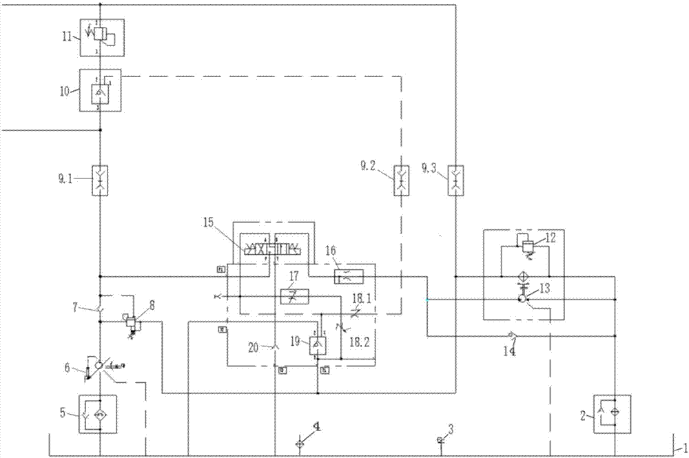
[0014] Such as figure 1 As shown, a temperature-controlled hydraulic system for a top drive drilling rig includes a hydraulic pump station, a temperature-controlled valve group, a main valve and a cooler; the main valve is provided with a heating overflow valve 11 for heating the oil circuit in the main valve, A first hydraulic control check valve 10 is connected in series on the oil inlet of the heating overflow valve 11 .

[0015] The hydraulic pump station includes a hydraulic oil tank 1 and an unloading valve 8. The hydraulic oil tank 1 is equipped with an oil temperature sensor 3 and an electric heater 4; the oil outlet of the hydraulic oil tank is provided with a variable plunger pump 6, which is connected to There are check valve 7 and unloading valve 8. An oil suction filter 5 is arranged between t...


PUM


Abstract

The invention discloses a temperature control hydraulic system for a top drive drilling rig. The temperature control hydraulic system for the top drive drilling rig comprises a hydraulic pump station, a temperature control valve set, a main valve and a cooler; the main valve is provided with a heating overflow valve and a first liquid-control opening check valve; the hydraulic pump station comprises a hydraulic oil tank, an unloading valve, an oil temperature sensor and an electric heater; the cooler is communicated with the hydraulic oil tank; the temperature control valve set comprises an electromagnetic reversing valve, a first speed adjusting valve, a second speed adjusting valve, a first throttling valve, a second throttling valve and a second liquid-control opening check valve; when the electromagnetic reversing valve is located at the middle position, oil of the hydraulic oil tank returns to the hydraulic oil tank through the unloading valve and the cooler; a first oil outlet of the electromagnetic reversing valve is communicated with the first speed adjusting valve and the cooler in sequence; and a second oil outlet of the electromagnetic reversing valve is connected with three oil ways. The system can adapt to the high temperature and low temperature environment requirements, performs self-adaptive heating or cooling on the oil tank and the main valve, and effectively reduces the manufacturing cost on the basis of guaranteeing reliability.

Description

technical field [0001] The invention relates to the technical field of geological drilling engineering hydraulic systems, in particular to a temperature-controlled hydraulic system for top drive drilling rigs. Background technique [0002] At present, most of the deep well drilling rigs, offshore and shallow sea oil drilling platforms, and construction special craft wells at home and abroad are equipped with top drive drilling devices. The top drive drilling device is also called top drive for short. The top drive drilling device can directly rotate the drill pipe from the upper space of the derrick, and send it down along the special guide rail to complete various drilling operations such as drill pipe rotation drilling, drilling fluid circulation, column connection, make-up and breakout, and back reaming. Top drive drilling rigs significantly increase the capability and efficiency of drilling operations and have become a standard product in the oil drilling industry. Due...

Claims


Application Information

Patent Timeline
Patent Type & Authority Patents(China)
IPC IPC(8): F15B11/00F15B21/04
CPCF15B11/00F15B21/042
Inventor 李福生孙茂张媛
Owner SHANGHAI LANSHI HEAVY IND MACHINERY
Why Eureka
Try Eureka