Complex prism for functional telescope and binocular telescope optical system thereof

A compound prism and optical system technology, applied in the field of optical systems, can solve problems such as inconvenient observation for users, achieve the effect of improving optical transmittance and maintaining stability

Active Publication Date: 2017-05-17
CHONGQING HAILANCHUANMA OPTICAL ELECTRIC TECH CO LTD
View PDF6 Cites 10 Cited by
  • Summary
  • Abstract
  • Description
  • Claims
  • Application Information

AI Technical Summary

Problems solved by technology

However, the existing telescopes generally only have the function of telescopic observation, while the usual laser ranging telescopes are for monocular observation, which is inconvenient for users to observe

Method used


Image

  • Complex prism for functional telescope and binocular telescope optical system thereof
  • Complex prism for functional telescope and binocular telescope optical system thereof
  • Complex prism for functional telescope and binocular telescope optical system thereof

Examples


Embodiment 1

[0025] Embodiment 1, HYLON-A prism and application example

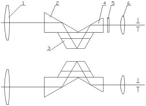
[0026] The HYLON-A prism is composed of the first half pentaprism 2, the roof prism 3 and the second half pentaprism 4, see figure 1 . Objective lens 1, HYLON-A prism and eyepiece 6 constitute a binocular telescope optical system. Adding a reticle 5 in one of the lens barrels has measurement or aiming functions corresponding to different reticles.

Embodiment 2

[0027] Embodiment 2, HYLON-A1 prism and application example

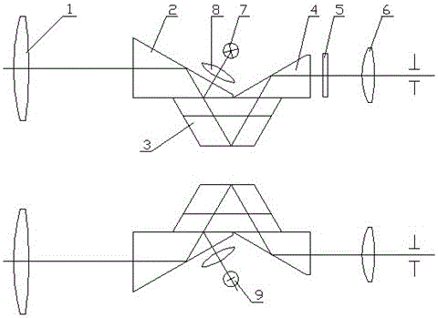
[0028] In this embodiment, the HYLON-A1 prism is formed by gluing three pieces of the first half pentaprism 2, the roof prism 3 and the second half pentaprism 4. It differs from the HYLON-A prism in that: the long rectangular surface of the half pentaprism 2 is coated with a spectroscopic film that reflects laser light and transmits visible light. See figure 2 . The objective lens 1, the HYLON-A1 prism, the reticle 5 and the eyepiece 6 constitute a telescopic optical system with the functions of aiming and binocular observation. Laser 7, laser receiver 9, lens 8, prism HYLON-A1, and objective lens 1 respectively constitute a laser emitting system and a laser receiving system. The above four systems form a binocular laser ranging telescope, see figure 2 . The measured laser signal is converted into data information by the signal processing circuit, and then the reticle 5 composed of transmissive liquid crystal...

Embodiment 3

[0029] Embodiment 3, HYLON-A2 prism and application examples

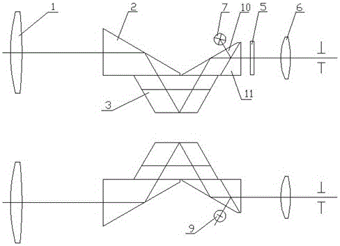
[0030] In this embodiment, the HYLON-A2 prism is made of four pieces of the first half pentaprism 2, the roof prism 3, the triangular prism 10 and the wedge prism 11. The difference between it and HYLON-A is that the second half pentaprism is made of a triangular prism 10 and a wedge prism 11 glued together, and the glued surface is coated with a spectroscopic film that reflects laser light and transmits visible light. See image 3 . The objective lens 1, the HYLON-A2 prism, the reticle 5 and the eyepiece 6 constitute a telescopic optical system with the functions of aiming and binocular observation. The laser 7 and the laser receiver 9 form a laser emitting system and a laser receiving system with the HYLON-A2 prism and the objective lens 1 respectively. The above four systems form a binocular laser ranging telescope, see image 3 . The measured laser signal is converted into data information by the signal pr...


PUM


Abstract

The invention discloses a complex prism for a functional telescope and a binocular telescope optical system thereof. The complex prism includes a first semi-pentaprism, a roof prism and a second semi-pentaprism. The first semi-pentaprism and the second semi-pentaprism have long right-angle surfaces which are adhesive to the bottom surface of the roof prism. A light incoming surface and a light emitting surface of the roof prism are on the same plane and are parallel to the roof ridge, such that an incoming optical axis and an outcoming optical axis of the complex prism are parallel. The binocular telescope optical system includes an objective lens, a complex prism, a reticle lens and an eye lens. The complex prism can obverse, collimate, transmit and receive laser rays and display laser rays.

Description

technical field [0001] The invention relates to the field of optical systems, in particular to a composite prism for a multifunctional telescope and an optical system for a binocular telescope. Background technique [0002] Telescopes have become a popular fashion consumer product. However, the existing telescopes generally only have the function of telescopic observation, while the common laser ranging telescopes are for monocular observation, which has the disadvantage of being inconvenient for users to observe. Design a telescope that not only has the function of binocular observation, but also can quickly measure the target distance and target speed by emitting laser light, and can simultaneously or selectively measure its own longitude and latitude, azimuth angle, elevation angle, altitude, horizontality, and north direction. In the field of view, the measured data can be directly displayed through transmissive liquid crystal (LCD) or OLED or projected through OLED or ...

Claims


Application Information

Patent Timeline
Patent Type & Authority Applications(China)
IPC IPC(8): G02B5/04G02B23/04G02B7/18
CPCG02B7/1805G02B23/04G02B5/04
Inventor 朱杰高明晓
Owner CHONGQING HAILANCHUANMA OPTICAL ELECTRIC TECH CO LTD
Why Eureka
Try Eureka