Composite thermal interface material composed of metal mesh and low-melting-point alloy

A technology of thermal interface materials and metal grids, applied in the field of thermally conductive materials, can solve problems such as short circuit faults, contamination of electronic components, overflow, etc.

Inactive Publication Date: 2017-05-24
CHINA EPRI ELECTRIC POWER ENG CO LTD +1
View PDF4 Cites 11 Cited by
  • Summary
  • Abstract
  • Description
  • Claims
  • Application Information

AI Technical Summary

Problems solved by technology

However, when the low melting point alloy melts, it is easy to overflow, which i

Method used


Image

  • Composite thermal interface material composed of metal mesh and low-melting-point alloy
  • Composite thermal interface material composed of metal mesh and low-melting-point alloy

Examples


example 1

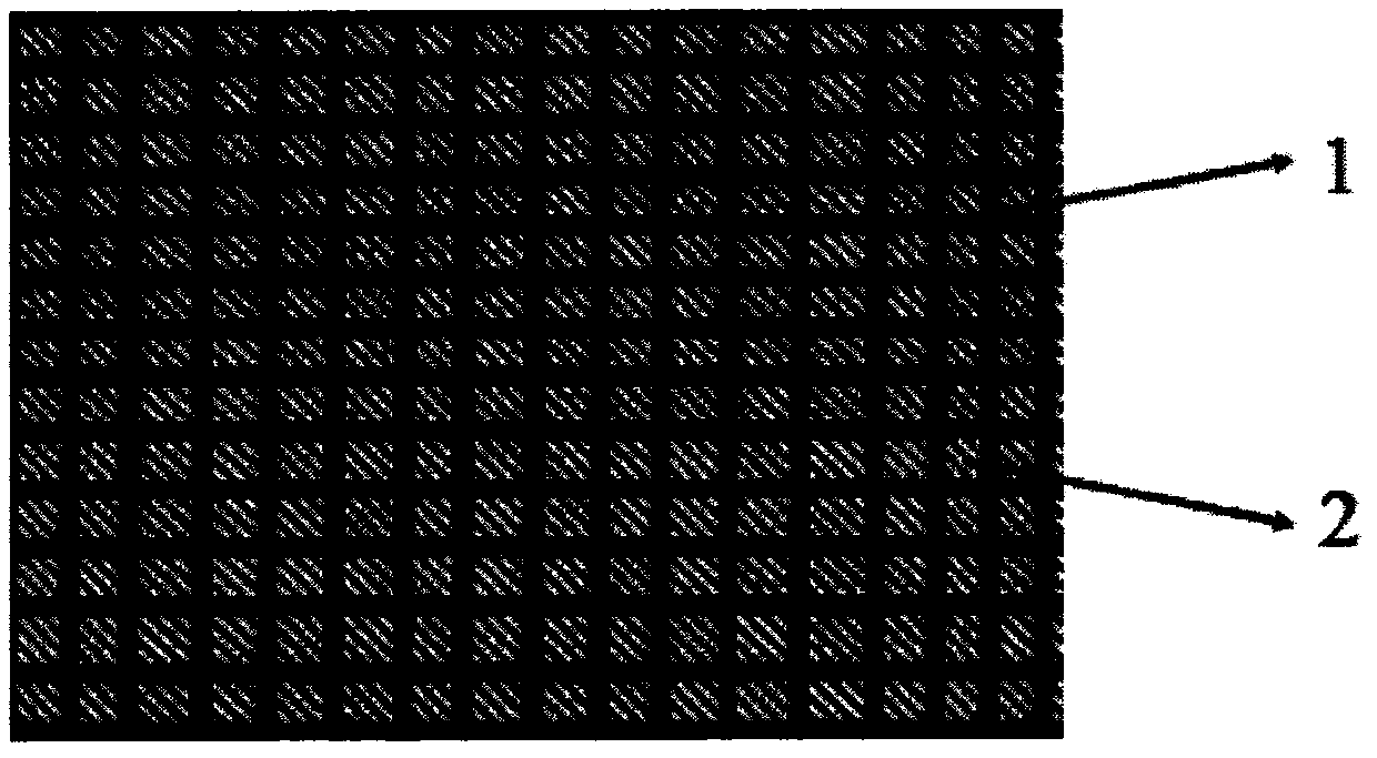
[0010] The composite thermal interface material provided in this embodiment is composed of a copper grid and a low melting point alloy, and the low melting point alloy is uniformly filled in the mesh holes of the copper grid. The mesh size of the copper grid is 1000 microns. The low melting point alloy is indium bismuth tin gallium alloy, the mass ratio is In100Bi66Sn33Ga1.2, and the melting point is 63°C. The thermal conductivity of the above composite thermal interface material was tested on the Longwin TIM LW-9389 steady-state heat flow method thermal conductivity tester (Taiwan Ruiling Technology Co., Ltd.). When the test temperature was 30°C, the thermal conductivity was 10W / (m k ); when the test temperature is 70°C, the thermal conductivity is 45W / (m·k).

example 2

[0012] The composite thermal interface material provided in this embodiment is composed of a copper grid and a low melting point alloy, and the low melting point alloy is uniformly filled in the mesh holes of the copper grid. The mesh size of the copper grid is 500 microns. The low melting point alloy is indium bismuth tin gallium alloy, the mass ratio is In100Bi62Sn31Ga16, and the melting point is 47°C. The thermal conductivity of the above composite thermal interface material was tested on the Longwin TIM LW-9389 steady-state heat flow method thermal conductivity tester (Taiwan Ruiling Technology Co., Ltd.). When the test temperature was 30°C, the thermal conductivity was 17W / (m·k ); when the test temperature is 60°C, the thermal conductivity is 52W / (m·k).

example 3

[0014] The composite thermal interface material provided in this embodiment is composed of a stainless steel grid and a low melting point alloy, and the low melting point alloy is evenly filled in the mesh holes of the stainless steel grid. The mesh size of the stainless steel grid is 1000 microns. The low melting point alloy is indium bismuth tin gallium alloy, the mass ratio is In100Bi66Sn33Ga1.2, and the melting point is 63°C. The thermal conductivity of the above composite thermal interface material was tested on the Longwin TIM LW-9389 steady-state heat flow method thermal conductivity tester (Taiwan Ruiling Technology Co., Ltd.). When the test temperature was 30°C, the thermal conductivity was 9W / (m·k ); when the test temperature is 70°C, the thermal conductivity is 41W / (m·k).


PUM

PropertyMeasurementUnit
Thermal conductivityaaaaaaaaaa

Abstract

The invention provides a composite thermal interface material composed of a metal mesh and a low-melting-point alloy; the low-melting-point alloy exists in mesh openings of the metal mesh in a solid form at room temperature, the low-melting-point alloy is melted at a work temperature and fills a gap of a heat transfer interface, and the metal mesh can prevent overflowing of the low-melting-point alloy, wherein the metal mesh is one of a copper mesh, a stainless steel mesh and a nickel mesh. The low-melting-point alloy is an indium-bismuth-tin-gallium alloy and has the melting point of 40-70 DEG C. The composite thermal interface material has the advantages of simple structure, high thermal conductivity, convenience in use, safety and reliability, and can avoid contamination or short circuit fault of equipment due to overflowing of liquid alloys.

Description

technical field [0001] The invention relates to the field of heat-conducting materials, in particular to a composite thermal interface material composed of a metal grid and a low melting point alloy. Background technique [0002] Thermal interface materials are widely used to improve the heat dissipation efficiency of electronic devices and electrical equipment. In actual work, the surface of the material that needs to be cooled in electronic devices and electrical equipment is in contact with the surface of the heat sink, thereby transferring heat to the heat sink, and then the heat is transferred to the environment by the heat sink, and finally realizes cooling for electronic devices and electrical equipment. purpose of cooling. However, there are very fine uneven gaps on the surface of the material that needs to be cooled and the surface of the heat sink in electronic devices and electrical equipment. If they are directly installed together, the actual contact area betwe...

Claims


Application Information

Patent Timeline
IPC IPC(8): C09K5/06
CPCC09K5/06
Inventor 查鲲鹏吴大雄倪君周建辉王航朱海涛雷清泉
Owner CHINA EPRI ELECTRIC POWER ENG CO LTD
Why Eureka
Try Eureka