Eureka AIR delivers breakthrough ideas for toughest innovation challenges, trusted by R&D personnel around the world.

Magnetic core air gap fixing structure assembly for core passing type Hall current sensor

A technology of fixed structure and Hall current, which is applied in the parts of electrical measuring instruments, voltage/current isolation, instruments, etc., can solve the problem of inability to perform linear compensation, difficult installation and fixation of magnetic cores, and increased manufacturing cost of Hall current sensors, etc. problems, to ensure the consistency of the air gap width and thermal expansion coefficient, simplify the temperature compensation circuit and installation process, and improve the measurement accuracy and production efficiency.

Active Publication Date: 2017-05-24
南京普肯传感科技有限公司
View PDF7 Cites 3 Cited by
  • Summary
  • Abstract
  • Description
  • Claims
  • Application Information

AI Technical Summary

Problems solved by technology

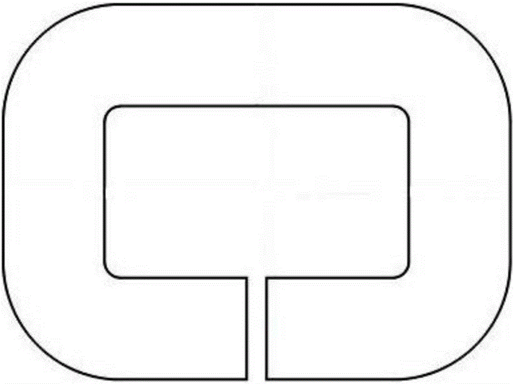
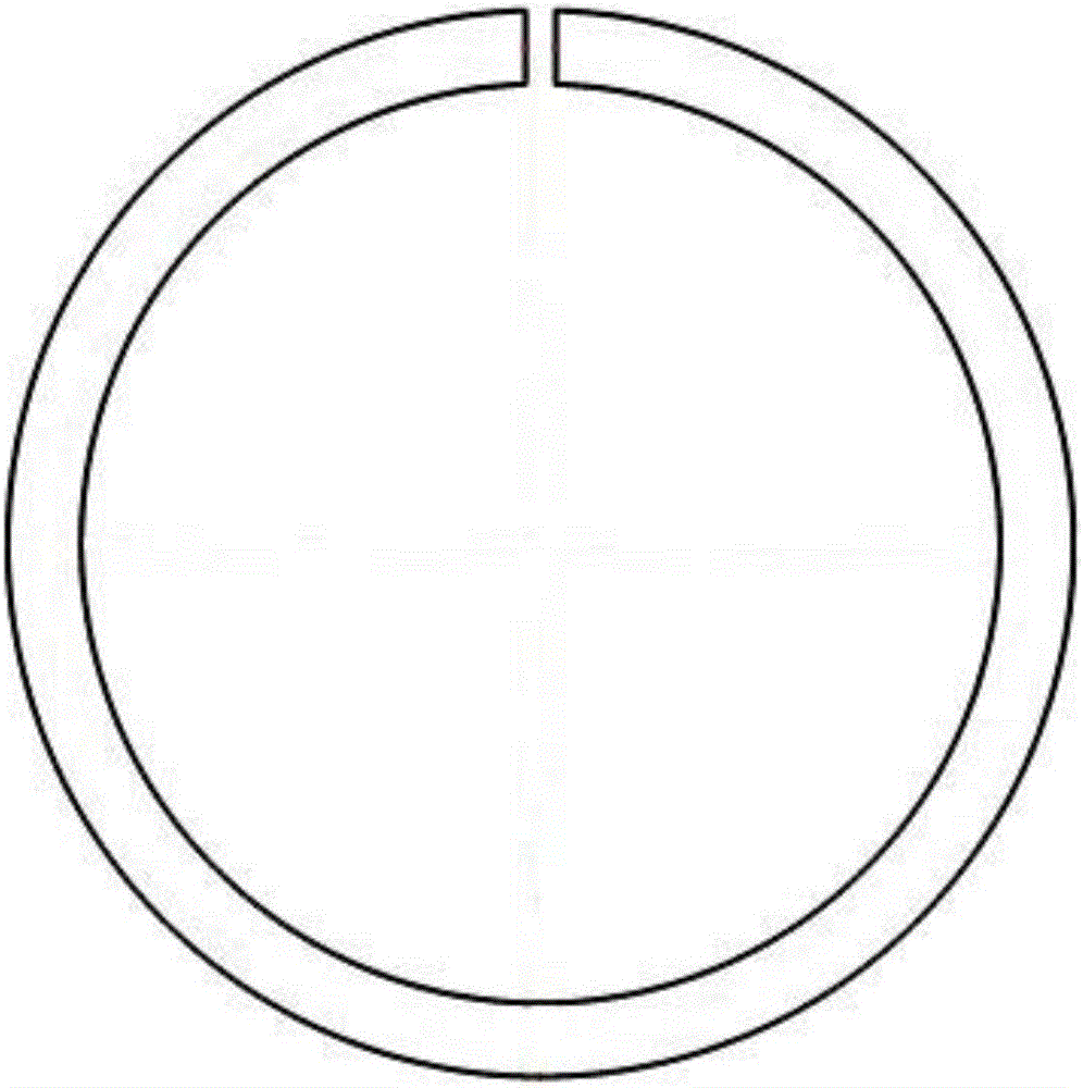
[0009] like figure 1 and 2 As shown, the Hall current sensor with a single magnetic core and single air gap structure has a relatively large remanence of the magnetic core, and the zero point of the Hall current sensor changes greatly, which seriously affects the measurement accuracy of the Hall current sensor.
In order to reduce the influence of remanence, the core is made of iron-nickel alloy material with low remanence, which will greatly increase the manufacturing cost of Hall current sensor
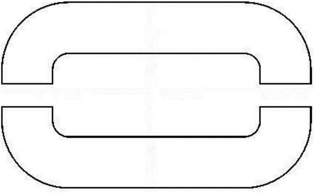
[0010] like image 3 and 4 As shown, the Hall current sensor with a single magnetic core and multiple air gaps is very difficult to install and fix the magnetic core. It is necessary to position the magnetic core in the plastic shell segment by segment, and place plastic blocks with the same width as the air gap one by one. The air gap is fixed with potting glue, but the potting glue takes time to cure, and the consistency of the air gap width cannot be ensured, which will affect the production efficiency and parameter consistency of the sensor in mass production
[0011] Hall current sensors with a single magnetic core, single or multiple air gap structures, the shape of the magnetic core is generally circular or square. When there are multiple air gaps, place plastic blocks with the same width as the air gap one by one. Zhonglai guarantees the consistency and stability of the air gap width, but under the condition of wide temperature range, since the deformation and stress of each part of the magnetic core cannot be consistent during machining, as the temperature changes, the plastic block and soft magnetic material The thermal expansion coefficient cannot be consistent, resulting in that the thermal expansion coefficient of the air gap width is not a constant constant, so that the output amplitude of the Hall current sensor varies nonlinearly with the temperature, and linear compensation cannot be performed, resulting in poor temperature stability of the Hall current sensor. Seriously affect the measurement accuracy of the Hall current sensor
[0012] Single magnetic core single or multiple air gap structure Hall current sensor, the magnetic core is not closed due to the magnetic circuit, as the core air gap width or number increases, the effective magnetic permeability of the magnetic core decreases rapidly, and the Hall current When the sensor measures the AC current, the primary and secondary cannot be tightly coupled. When the primary current-carrying conductor is in different positions in the core hole of the Hall current sensor, the output amplitude and waveform of the sensor will change greatly, which will seriously affect the Hall current sensor. Operating Bandwidth and Measurement Accuracy of Current Sensors

Method used


Image

  • Magnetic core air gap fixing structure assembly for core passing type Hall current sensor
  • Magnetic core air gap fixing structure assembly for core passing type Hall current sensor
  • Magnetic core air gap fixing structure assembly for core passing type Hall current sensor

Examples


Embodiment Construction

[0058] like Figure 5-12 As shown, the present invention discloses a magnetic core air gap fixed structural assembly for a core-through Hall current sensor, including a single magnetic core air gap fixed structural assembly and a double magnetic core air gap fixed structural assembly,

[0059] The single magnetic core air gap fixing structure component includes a single magnetic core and when it is necessary to fix the single magnetic core with a frame or skeleton, the single magnetic core includes one or an even number of air gaps;

[0060] Single magnetic core includes laminated riveted single magnetic core with air gap and wound single magnetic core with air gap;

[0061] Figure 5-10 As shown, the laminated riveted single magnetic core with air gap is provided with fixing holes or positioning slots when necessary, and the non-magnetic conductive metal sheet is riveted or welded on the top layer or the outermost upper and lower layers of the magnetic core. The pin is weld...


PUM


Abstract

The invention relates to the field of a magnetic core fixing structure assembly of a Hall current sensor, in particular to a magnetic core air gap fixing structure assembly for a core passing type Hall current sensor. The magnetic core air gap fixing structure assembly is characterized in that a fixing hole or a positioning groove is formed in a single magnetic core with an air gap formed by lamination riveting and punching; a non-conductive metal sheet is riveted and punched or welded onto the upper top layer or the outermost upper and lower layers of the single magnetic core; the non-conductive metal sheet is welded onto the outer side surface or the top of the magnetic core air gap position by a single magnetic core with an air gap formed by winding; when the two single magnetic cores with the same dimension or the single magnetic cores with one or even air gaps and one fixing frame or framework is used, the two single magnetic cores with the air gaps are arranged on the upper and lower surfaces of the fixing frame or the framework; the even number of air gaps are in staggered arrangement or symmetrical distribution or uniformly divide the whole magnetic paths; the side surface of the fixing frame or the framework is provided with an insertion groove communicating the air gaps of the magnetic core; the conversion plate is inserted in the insertion groove; a Hall element arranged in the magnetic core air gap is directly connected with a printed circuit board or is connected with the printed circuit board through a conversion plate.

Description

technical field [0001] The invention relates to the field of magnetic core fixing structural components of a Hall current sensor, in particular to a magnetic core air gap fixing structural component for a core-through Hall current sensor. Background technique [0002] With the development of power electronics technology, various current conversion technologies and AC numerical control devices are changing with each passing day. In these automatic control fields that use current as the measurement and monitoring object, especially in the fields of electric vehicles and rail transit, not only current sensors are required Good consistency, high reliability, and high-precision measurement in a wider temperature range; and in the case of weak global economic recovery and increasingly fierce market competition, higher cost-effective requirements are put forward for current sensors. In order to adapt and meet In response to market demand, manufacturers at home and abroad have tried...

Claims


Application Information

Patent Timeline
Patent Type & Authority Applications(China)
IPC IPC(8): G01R15/20G01R1/02
CPCG01R1/02G01R15/202
Inventor 邹高芝魏义松苏本社
Owner 南京普肯传感科技有限公司
Why Eureka
Eureka Blog
Learn More