Three-dimensional imaging device and method based on time correlation

A three-dimensional imaging and time-correlated technology, which is applied in the directions of measuring devices, electromagnetic wave re-radiation, instruments, etc., can solve the problems of high device cost, affecting the imaging field of view, and difficulty in realizing large-scale surface detector integration, etc., and achieve low cost , The effect of simple device structure

Active Publication Date: 2017-05-24
SHANGHAI INST OF OPTICS & FINE MECHANICS CHINESE ACAD OF SCI
View PDF3 Cites 10 Cited by
  • Summary
  • Abstract
  • Description
  • Claims
  • Application Information

AI Technical Summary

Problems solved by technology

This imaging method benefits from the concentration of irradiated energy and the high sensitivity of single-point detectors, and usually has a high detection signal-to-noise ratio, but its imaging resolution suffers from the fact that the laser beam is easily divergent due to atmospheric disturbances during long-distance detection. resulting in lower imaging resolution
In addition, scanning imaging is limited by the scanning rate, and the imaging rate is slow when scanning and detecting a large field of view, which is not suitable for three-dimensional information acquisition of moving targets
In order to overcome the problems of low resolution and slow imaging rate in scanning imaging, the point detector is integrated into an area array detector, and a single exposure imaging can be realized by performing large-scale flash illumination and area detection on the target.
There are usually two ways to extract target distance information in this imaging method. One is that each pixel in the area array detector works independently, and independently completes the information extraction of the intensity and arrival time of the returned signal. This method is affected by the device integration technology. However, it is generally difficult to achieve large-scale surface detector integration, which affects the imaging field of view; another ranging technology achieves distance information extraction through accurate and fast exposure through range gating, such as the existing enhanced charge-coupled Devices (ICCD) can realize exposure detection on the order of nanoseconds, but the cost of such devices is high, especially in the infrared band.

Method used


Image

  • Three-dimensional imaging device and method based on time correlation
  • Three-dimensional imaging device and method based on time correlation
  • Three-dimensional imaging device and method based on time correlation

Examples


Embodiment Construction

[0030] The present invention will be further described below in conjunction with the accompanying drawings.

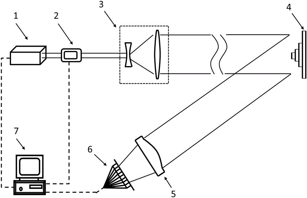
[0031] figure 1 It is a structural schematic diagram of the three-dimensional imaging device based on time correlation of the present invention. It can be seen from the figure that the three-dimensional imaging device based on time correlation of the present invention includes a transmitting system, a receiving system and a control system:

[0032] Described transmitting system comprises laser device 1, light intensity modulator 2 and laser beam expander mirror 3, described receiving system comprises receiving telescope 5 and area array detector 6, described control system is industrial computer 7, along the described The output optical path of the laser 1 is the light intensity modulator 2 and the laser beam expander 3 in sequence, and the laser beam expander 3 shapes and expands the laser beam into a beam that is uniformly distributed in space and irradiates the targ...


PUM


Abstract

The invention provides a three-dimensional imaging device and method based on time correlation. The three-dimensional imaging device is formed by a laser, a light intensity modulator, a laser beam-expanding lens, a reception telescope, an area-array detector and an industrial control computer. The three-dimensional imaging method of the three-dimensional imaging device based on time correlation is realized through the following three steps: 1) obtaining two-dimensional image information of an object through single exposure imaging; 2) obtaining elevation information of each image point on the two-dimensional image of the object through multiple exposure detection and time correlation operation; and 3) combining the two-dimensional image information and the elevation information of the corresponding image points to form a three-dimensional image of the object. The method can be used for constructing a large-visual-field, high-resolution and low-cost three-dimension laser imaging radar.

Description

technical field [0001] The invention relates to laser three-dimensional imaging, in particular to a three-dimensional imaging device and imaging method based on time correlation. Background technique [0002] With the advancement of technology, 3D imaging is receiving more and more attention and research. The rich information carried by 3D images and its geometric invariant characteristics make this technology play a huge role in the fields of urban planning, industrial inspection, automatic navigation and military target recognition. In the field of remote sensing observation, relatively mature laser 3D imaging technology can be divided into scanning imaging and non-scanning imaging according to the image acquisition method. [0003] Scanning imaging uses laser illumination and high-sensitivity point detection to scan point by point or line by line to obtain the light intensity reflection information and distance information of each point on the target, thereby realizing t...

Claims


Application Information

Patent Timeline
Patent Type & Authority Applications(China)
IPC IPC(8): G01S17/89
CPCG01S17/89
Inventor 薄遵望龚文林韩申生陈明亮
Owner SHANGHAI INST OF OPTICS & FINE MECHANICS CHINESE ACAD OF SCI
Why Eureka
Try Eureka